Wmvav controller wiring, Component & system wiring 18, Component wiring diagram – WattMaster VAV User Manual
Page 18: Wmvav controller, All comm loop wiring is straight thru, T to t r to r shld to shld, Vav-wmvavwir1a.cdr, 1 of 2 line voltage, 24vac
Component & System Wiring
18
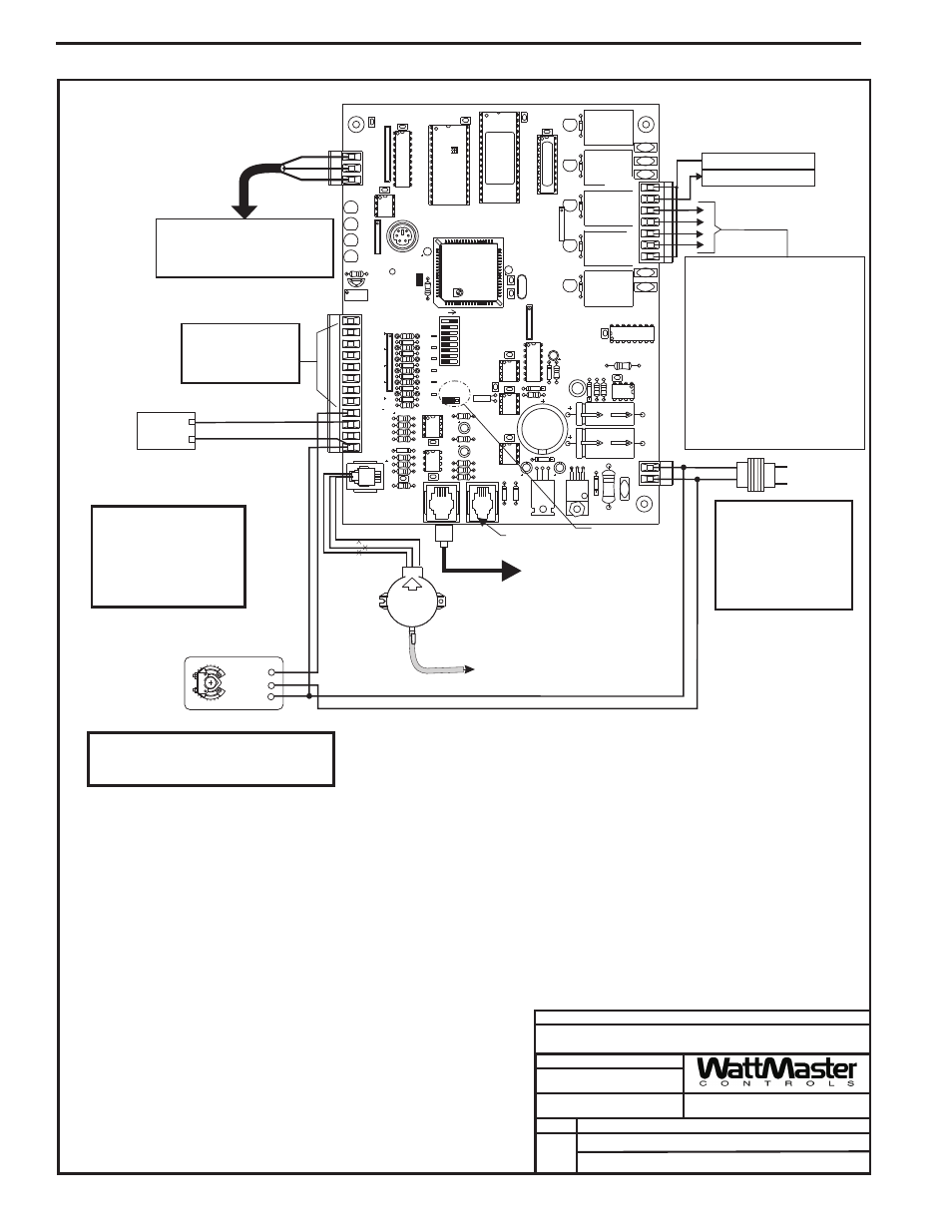
WMVAV Controller Wiring
Notes:
1.)24 VAC Must Be Connected So That
All Ground Wires Remain Common.
4.)When Humidity Sensor Is To Be
Installed A 250 Ohm Resistor Must Be
Installed On The Ground Side Of The
Sensor And Pull Up Resistor PU5
Must Be Removed From The
Controller. See Humidity Sensor
Wiring Diagram In The WMVAV
section of this manual.
5.)If The Slide Adjust Option Is Used On
The Room Sensor , The AUX
Connection Must Be Wired To AIN7.
The Fan Proof Of Flow Switch,
Which Normally Connects To AIN7, Is
Not Available For Use When The
Slide Adjust Option Is Used.
3.)All Communication Wiring To Be 18
Ga. Minimum, 2 Conductor Twisted
Pair With Shield. Belden #82760 Or
Equivalent.
2.)All Wiring To Be In Accordance With
Local And National Electrical Codes
and Specifications.
FILENAME
DATE:
B. Crews
DESCRIPTION:
PAGE
DRAWN BY:
Component Wiring Diagram
JOB NAME
05/12/04
VAV-WMVAVWIR1A.CDR
WMVAV Controller
1 of 2
Line Voltage
All Comm Loop Wiring Is
Straight Thru
24VAC
24VAC
GND
GND
Local Loop RS-485
9600 Baud
Analog Inputs
See Individual Sensor
Wiring Diagrams For
Detailed Sensor Wiring
Connect To Next Controller,
MiniLink PD Or System Manager
On Local Loop
G - Fan ON/OFF Only
R - 24VAC
Relay Output Dry Contacts
R2 Thru R5 May Be User Configured
For The Following:
1 - Heating (Aux. Heating)Stages
2 - Cooling (Compressor) Stages
3 - Warm-up Mode Command For Boxes
4 - Reversing Valve (Air To Air Heat Pumps)
5 - Gas Reheat Control For Dehumidification
6 - Exhaust Fan Interlock
7 - Preheat Coil
8 - Alarm Relay
9 - Override
10 - Occupied
11 - Economizer
Note: Up To 16 More Relays Are Available By
Adding Relay Expansion Boards. All
Expansion Board Relay Outputs Are User
Configurable As Listed Above.
3
2
1
Economizer
Actuator
(Belimo Shown)
Consult Factory For
Other Manufacturers
Wiring Connections
Connect Tubing To High Pressure
Port (Bottom Tube) and Route To Static
Pressure Pickup Probe Located In Unit
Discharge. Leave Port Marked “Lo” Open
To Atmosphere
S.P.
Transducer
Splice If Req’d
Connect To
Expansion Board
Base (When Used)
Not Used
Jumper Must
Be In 0-5V Position
As Shown
RL
Y1
D1
D2
D3
D4
D5
RAM
C3
C2
U6
PHILIPS
CX6
C1
CX2
U2
PAL
CX4
U4
TUC-5R PLUS
YS101816 REV. 2
V1
V2
V3
V5
V4
TB2
4
NETWORK
TOKEN
16
32
8
SW1
ADD
2
1
ADDRESS
V6
POWER
GND
24VAC
L1
D16
R6
C9
SC1
R1
1
U1
1
MC34064A
D13
C16
9936
VR2
TB4
R27
C13
R10
VR1
C19
C18
NE5090NPB3192
0PS
U8
CX8
U9
X1
R7
D10
R13
D12
C7
CX10
U10
CX12
U12
U14
CX14
PJ3
PJ2
PJ1
EXPANSION
PRESSURE
SENSOR
T'STAT
C17
D15
R26
C20
R25
R24
R22
U15
CX13
U13
C15
R19
R15
C14
D18
D17
PU1
PU2
PU3
PU4
PU5
PU7
D6
D7
D8
D9
D11
D14
C12
C10
0-5
VDC
0-1
VDC
JP1
C1
1
X2
GND
TB3
INPUTS
GND
GND
+VDC
AIN1
AIN2
AIN3
AIN4
AIN5
AOUT1
AOUT2
AIN7
RN4
1
RN5
RS-485
CX5
U5
R
TB1
SHLD
T
COMM
COMM
RN3
1
RN1
U1
CX1
1
LD6
COMM
PWR
LD7
LED1
LED2
LD9
LD8
R1
U7
RV1
VREF ADJ
R28
+VREF
5.11V
TEST POINT
EWDOG
D19
RN2
1
COM1-3
COM4-5
R5
R4
R3
R2
R1
RL
Y2
RL
Y3
RL
Y4
RL
Y5
CX15
(1 MEG)
HH
P1
C21
CX3
EPROM
U3
+
Supply Fan
Variable Frequency Drive
(By Others)
_
VFD 0-10VDC Input
GND
The VFD Unit Must Be
Configured For 0-10VDC
Input. The Input Resistance
At The VFD Must Not Be
Less Than 1000 Ohms When
Measured At The VFD
Terminals With All Input
Wires Removed.
Warning:
24 VAC Must Be Connected So That All Ground
Wires Remain Common. Failure To Do So Will
Result In Damage To The Controllers.
T to T
R to R
SHLD to SHLD
Size Transformer For
Correct Total Load. WMVAV
Controller = 8 VA Power
Consumption. If Economizer
Option Is Used
The Economizer Actuator
VA load Must Also Be
Considered When Sizing
The Transformer.