Gpc wiring, Component & system wiring 53, Gpc controller – WattMaster VAV User Manual
Page 53: Gpc controller address switch setting, Address add address add
Component & System Wiring
53
DATE:
B. Crews
DESCRIPTION:
PAGE
DRAWN BY:
Controller Wiring
JOB NAME
05/12/04
W-GPC-Control1.CDR
OE330 GPC
1
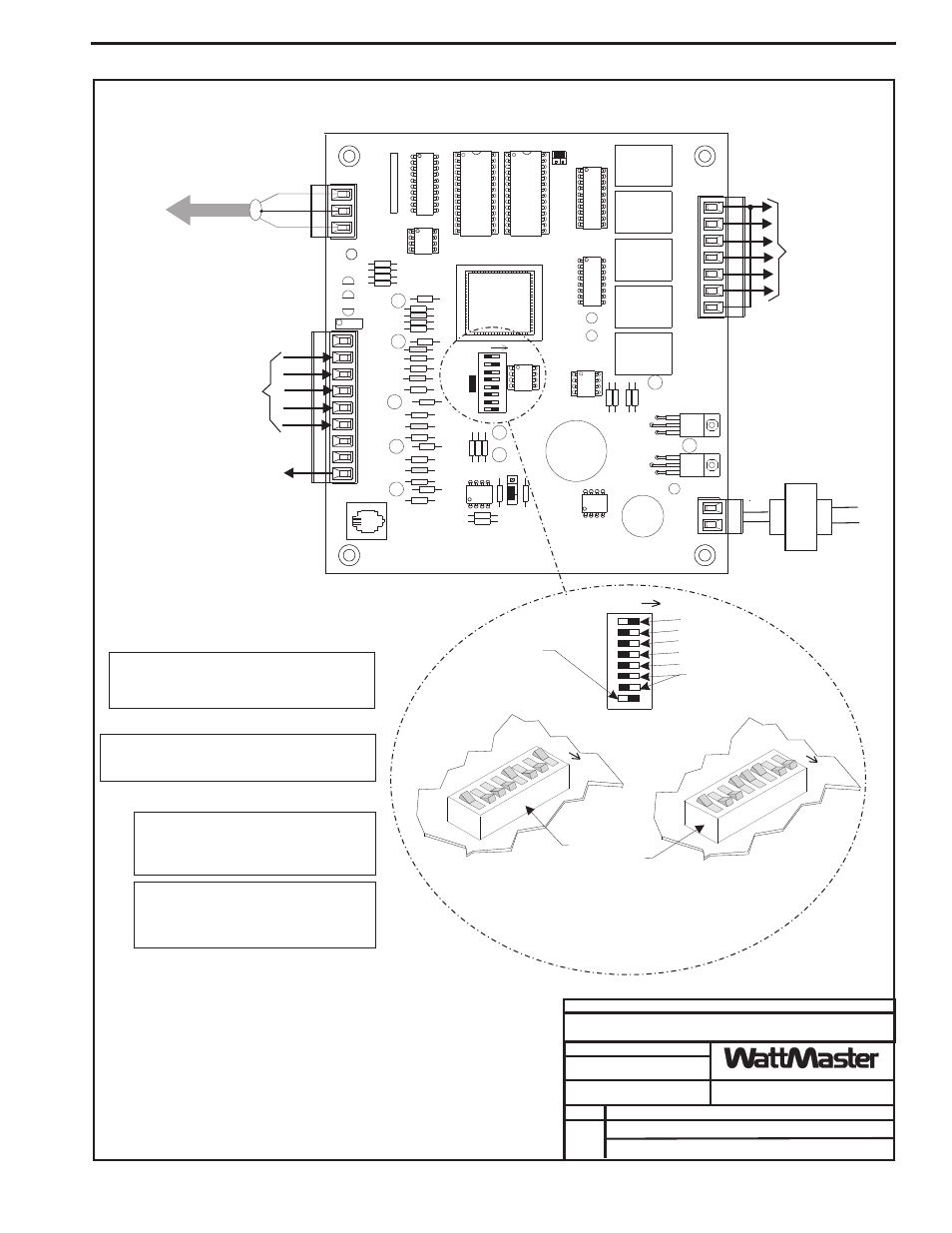
1.)24 VAC Must Be Connected So
That All Ground Wires Remain
Common.
3.)All Communication Wiring To Be 18
Ga. Minimum, 2 Conductor Twisted
Pair With Shield. Belden #82760 Or
Equivalent.
4.)It Is Recommended That All
Controllers Address Switches Are
Set Before Installation.
2.)All Wiring To Be In Accordance With
Local And National Electrical Codes
and Specifications.
Relay Output(s) To
Device(s) As
Required
By Application
Analog Input(s)
And/Or Digital
Input(s) From
Devices
As Required By
Application
Analog Output
To Device (WhenUsed)
(0-10 VDC)
Notes:
GPC Controller
Caution!
GPC Controllers Must Have Address Switches Set
Between 1 And 60.
Note:
The Power To The GPC Controller Must Be
Removed And Reconnected After Changing The
Address Switch Settings In Order For Any Changes
To Take Effect.
Caution:
Disconnect All Communication Loop Wiring
From The GPC Controller Before Removing Power
From The GPC Controller. Reconnect Power And
Then Reconnect Communication Loop Wiring.
Note:
Set-up, Programming And Monitoring Of The General
Purpose Controller Requires The Use Of A Personal
Computer And Prism Software.
12V
LINE
VOL
T
AGE
AIN
1
2
3
4
5
GND
GND
AIN
AIN
AIN
AIN
RELAY
OUTPUT
COM
1-3
OUT
OUT
1
2
COM
4-5
OUT
OUT
OUT
3
4
5
24VAC
24VAC
GND
GND
PWR
COMM
T
T
SHLD
SHLD
LD4
REC.
AOUT
4-5
OUT
COMM
TEST
32K
8K
RAM
EPROM
ADDRESS
ADD
PRESSURE
SENSOR
485
COMM
R
R
YS101564
EWDOG
0-5
VDC
0-1
VDC
PU1
PU2
PU3
PU4
PU5
GPC Controller Address Switch Setting
Local Loop
9600 Baud
See Note 1
16
8
4
2
1
Caution!
GPC Controller Must Have Address Switch Set Between 1 And 60
Address Switch Shown Is
Set For Address 9
Address Switch Shown Is
Set For Address 28
Controller
Address Switch
This Switch Must Be
In The ON Position
As Shown
These Switches Should Be
In The OFF Position
As Shown
ADDRESS
ADD
ADDRESS
ADD
ADDRESS
ADD
Required VA For
Transformer = 8 VA Min.
C
O
N
T
R
O
L
S
GPC Wiring