4 slot expansion base board wiring, Component & system wiring 28, Component wiring diagram – WattMaster VAV User Manual
Page 28
Component & System Wiring
28
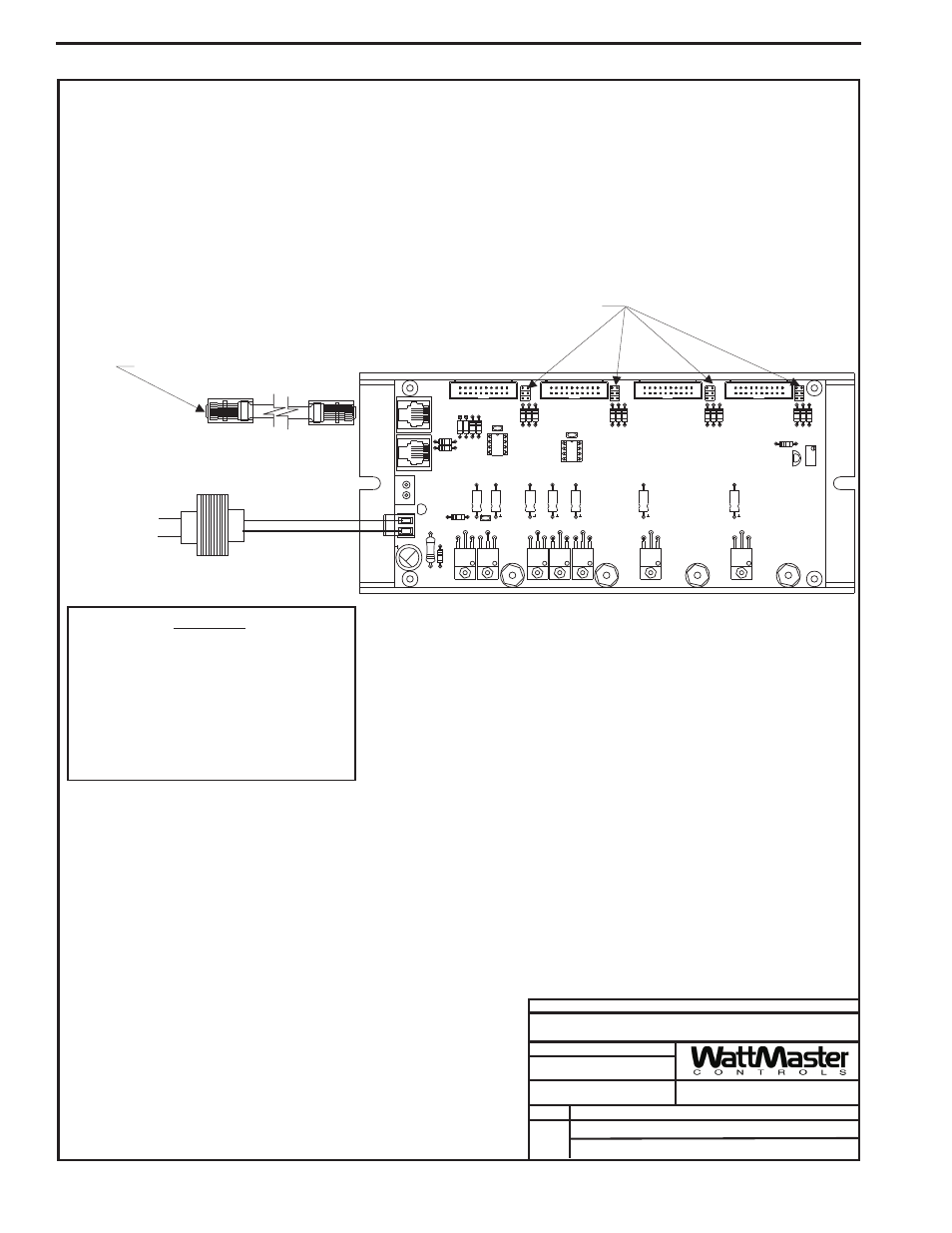
Notes:
1.)All Wiring To Be In Accordance With
Local And National Electrical Codes
and Specifications.
FILENAME
DATE:
B. Crews
DESCRIPTION:
PAGE
DRAWN BY:
Component Wiring Diagram
JOB NAME
03/24/04
VAV-OE353-4SLOTEXP.CDR
OE353 - 4 Slot Expansion Base Board
1
Connect To Unit Controller Board
Transformer Load = 14VA
WARNING!!
Observe Polarity! All boards must be wired with
GND-to-GND and 24VAC-to-24VAC.
Failure to observe polarity will result in damage
to one or more of the boards. Expansion Boards
must be wired in such a way that power to both
the expansion boards and the
controller are always powered together. Loss of
power to the expansion board will cause the
controller to become inoperative until power is
restored to the expansion board.
Line Voltage
24VAC
GND
Jumpers Must Be Set
According To Type Of
Expansion Board Used
See Expansion Board
Specific Wiring For
Jumper Settings
JP2
VR2
7824CT
R20
C8
TB2
D3
VR4
7812CT
VR3
7805ACT
VR5
VR6
7824CT
7824CT
C1
PWR
LD1
24VAC-IN
GND
GND
TB1
R19
PJ2
+24VDC-OUT
R17
PJ1
R15
D1 D2
LM358N
P82B715P
C3
C2
CX3
U1
C4
C5
U2
R3
R14
R13
CX1
R2
R1
P1
JP1
CX2
P2
7824CT
VR7
7824CT
4 SLOT MODULAR I/O BD.
VR8
YS101782
C6
R5
R4
R6
P3
R9
R8
R7
JP3
C7
VR1
R18
R11
R16
R10
P4
JP4
R12
4 Slot Expansion Base Board Wiring