Gpc-17 wiring, Component & system wiring 54, Optional analog output board – WattMaster VAV User Manual
Page 54: Gpc-17 controller, Optional relay expansion board, Ribbon connector
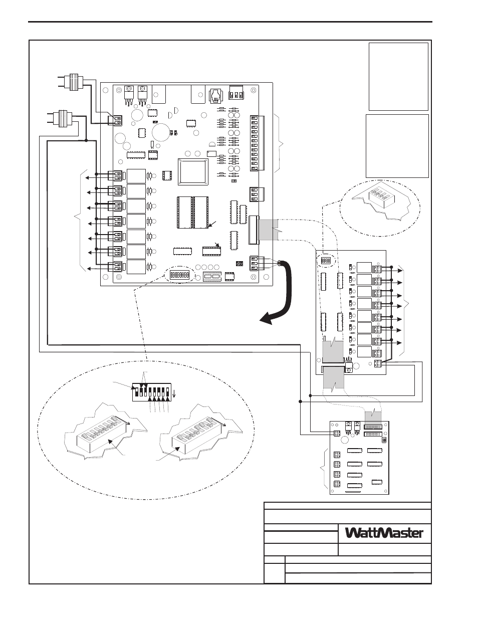
Component & System Wiring
54
Note:
Set-up, Programming
And Monitoring Of
The GPC-17
Controller Requires
The Use Of A
Personal Computer
And Prism Software.
1.)24 VAC Must Be Connected So
That All Ground Wires Remain
Common.
3.)All Communication Wiring To Be 18
Ga. Minimum, 2 Conductor Twisted
Pair With Shield. Belden #82760 Or
Equivalent.
4.)It Is Recommended That All
Controllers Address Switches Are
Set Before Installation.
2.)All Wiring To Be In Accordance With
Local And National Electrical Codes
and Specifications.
Local Loop RS-485
Communications To Other
Controllers
And/Or System Manager
Ribbon Connector
Optional
Analog
Output
Board
Ground
24V
All switches
(1 thru 4)
must be in the
“ON” position
EPROM
RAM
PAL
PIN 1
PIN 1
PIN 1
PIN 1
CPU
+V
+V
1
3
4
5
6
7
8
G
G
2
ANALOG
INPUTS
GND
SIG
+5V
ANALOG
OUTPUTS
A1
A2
G
T
SH
R
GND
24VAC
GPC-17 Controller
T
SH
R
K1
R1
R2
R3
R4
R5
R6
R7
R8
K2
K3
K4
K5
K6
K7
Line Voltage
Line Voltage
See Note 1
16
8
4
2
1
Address Switch Shown Is
Set For Address 1
Address Switch Shown Is
Set For Address 13
Controller
Address Switch
This Switch Must Be
In The ON Position
As Shown
These Switches Should Be
In The OFF Position
As Shown
ADD
ADD
ADD
The Address For Each Controller
Must Be Unique To The Other Controllers
On The Local Loop
Required VA For Transformer
Each Controller = 10 VA Min.
Note:
All Circuit Board
Contacts Are N.O.
All Contacts Are
Rated For 2 Amps
@ 24VAC Pilot
Duty Only
Do Not Apply Any
Voltage Greater
Than 24VAC
!
!
!
Caution!
Controller Must Have Address Switch Set Between 1 and 60
24V
COM
ANALOG OUT1
ANALOG OUT2
W
A
TTMASTER
ANALOG
OUTPUT
BOARD
YS101428
REV
.1
ADDR
+
-
+
-
1
2
LD1
PWR
ANALOG OUT3
ANALOG OUT4
+
-
+
-
RN1
Optional Relay Expansion Board
Relay Outputs
To Devices As
Required
By Application
Analog Inputs And/Or
Digital Inputs
From Devices As
Required By
Application
Relay
Outputs to
Devices
As
Required
By
Application
Analog Output
To Device
(0-10 VDC)
FILENAME
DATE:
DESCRIPTION:
PAGE
DRAWN BY:
GPC-17 Controller
1
JOB NAME
W-GPC-17CNTRL1A.CDR
OE310-21-GPC
B. Crews
05/12/04
C
O
N
T
R
O
L
S
Ribbon Connector
GPC-17 Wiring