Component & system wiring 31 – WattMaster VAV User Manual
Page 31
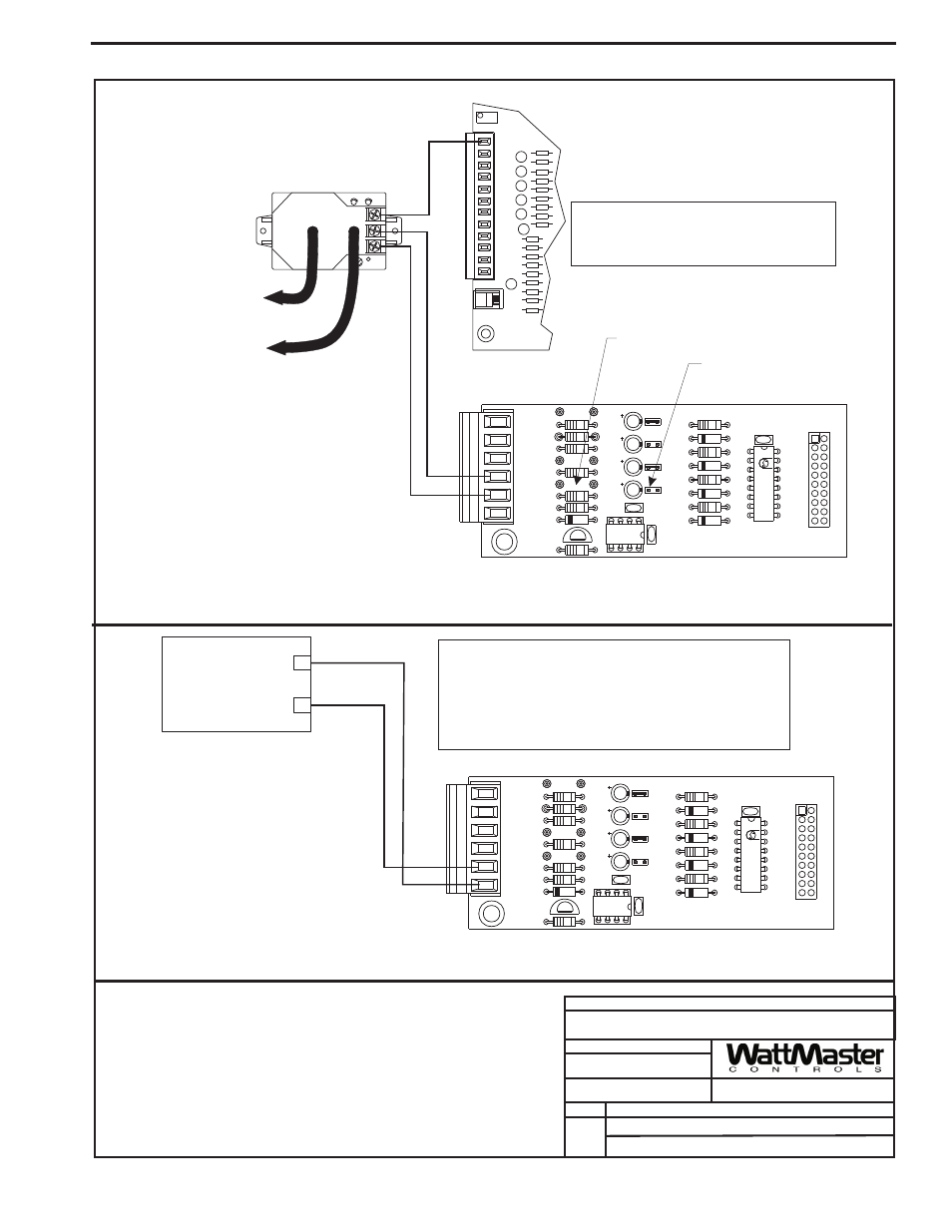
Component & System Wiring
31
Notes:
1.)All Wiring To Be In Accordance With
Local And National Electrical Codes
and Specifications.
FILENAME
DATE:
B. Crews
DESCRIPTION:
PAGE
DRAWN BY:
Component Wiring Diagram
JOB NAME
OE354 - 4 Analog Input 1 Analog Output Expansion Board
3 of 3
EXPANSION
SENSOR
PRESSURE
GND
7
AIN
AOUT2
AOUT1
AIN
GND
GND
5
AIN
AIN
AIN
4
3
2
AIN
1
+VDC
INPUTS
HIGH
LOW
-
+
+
+
VAV/CAV Unit Controller Board
Building Pressure Sensor
Tubing To Building
Pressure Sensing Location
Tubing To Atmospheric
Pressure Sensing Location
-
+
Jumper J04 Must Be Off
As Shown For Proper
0-5VDC Operation
Warning
:
24 VAC Must Be Connected So That All Ground
Wires Remain Common. Failure To Do So Will
Result In Damage To The Controllers.
Input #12 - Relief Pressure Sensor - Wiring
Output #3 - Relief Fan VFD Signal - Wiring
JO3
JO3
JO4
JO4
JO2
JO2
JO1
JO1
CX2
CX2
R10
R10
AOUT1
AOUT1
AIN4
AIN4
TB1
TB1
GND
GND
AIN2
AIN2
AIN3
AIN3
AIN1
AIN1
PU4
PU4
U2
U2
D5
D5
Q1
Q1
R8
R8
R9
R9
LM358
LM358
C5
C5
C1
C1
R7
R7
R6
R6
R5
R5
PU3
PU3
C4
C4
C3
C3
C2
C2
PU2
PU2
PU1
PU1
4 ANALOG IN MOD. I/O BD.
4 ANALOG IN MOD. I/O BD.
R3
R3
PCF8591P
PCF8591P
YS101784
YS101784
D4
D4
R4
R4
D3
D3
D1
D1
D2
D2
R2
R2
R1
R1
CX1
CX1
U1
U1
P1
P1
Pullup Resistor PU4 Must Be
Removed
+
Relief Fan Variable Frequency Drive
(By Others)
_
VFD 0-10VDC Input
GND
Warning:
The VFD Unit Must Be configured for 0-10VDC input.
The input resistance at the VFD must not be less than
1000 ohms when measured at the VFD terminals with
all input wires removed. Higher voltages or lower
resistance will cause improper operation and could
result in damage to circuit boards
03/24/04
VAV-OE354-4ANALOGIN1OUT.CDR
4 Analog Input 1 Analog Output Expansion Board Wiring (Cont’d)