Humidity sensor wiring, Component & system wiring 24 – WattMaster VAV User Manual
Page 24
Component & System Wiring
24
4-20
mA
4-20
mA
V
A
Co
rD
C
V
A
Co
rD
C
GNDGND
0-5V
or
0-10V
0-5V
or
0-10V
4 4
4 4
5 5
6 6
ON
ON
ON
ON
3 3
3 3
2 2
2 2
1 1
1 1
Zero
Zero
Span
Span
Notes:
1.)All Wiring To Be In Accordance With
Local And National Electrical Codes
and Specifications.
FILENAME
DATE:
B. Crews
DESCRIPTION:
PAGE
DRAWN BY:
WMVAV Controller Wiring
JOB NAME
02/21/08
VAV-HumidSensorWire1B.CDR
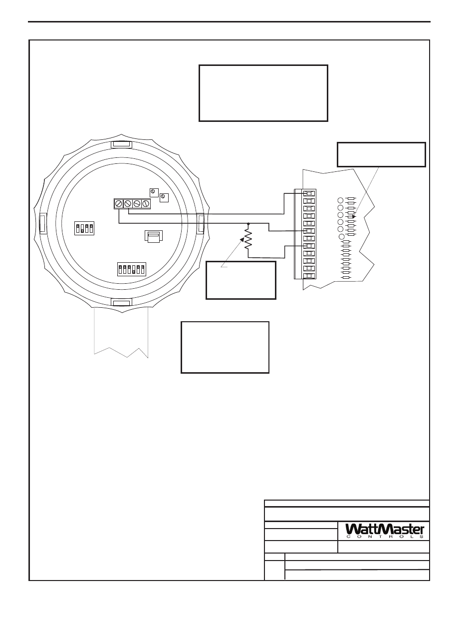
Humidity Sensor To
1
GND
INPUTS
GND
AOUT1
AOUT2
GND
+VDC
AIN1
AIN2
AIN3
AIN4
AIN5
AIN7
Outdoor
Air Humidity
Sensor - 4-20mA
WMVAV Controller Board
250 Ohm
Resistor
(Shipped With Sensor)
To be Installed Between
AIN5 and GND
Note:
If Remote Occupied Contact Is
Required When Humidity
Sensor Is Used, The Remote
Occupied Contact Must Be
Relocated To AIN2 On The 4
Analog Input 1 Analog Output
Expansion Board.
The Pull-up Resistor (PU5)
Must Be Removed
When Using A 4-20ma Device
Warning:
It is very important to be certain that all wiring
is correct as shown in the wiring diagram
below. Failure to observe the correct polarity
will result in damage to the Humidity Sensor or
controller.
Humidity Sensor Wiring