Component & system wiring 46, Minilink polling d evice commlink t erminals, 24 v a c class 2 t ransformer – WattMaster VAV User Manual
Page 46: Philips
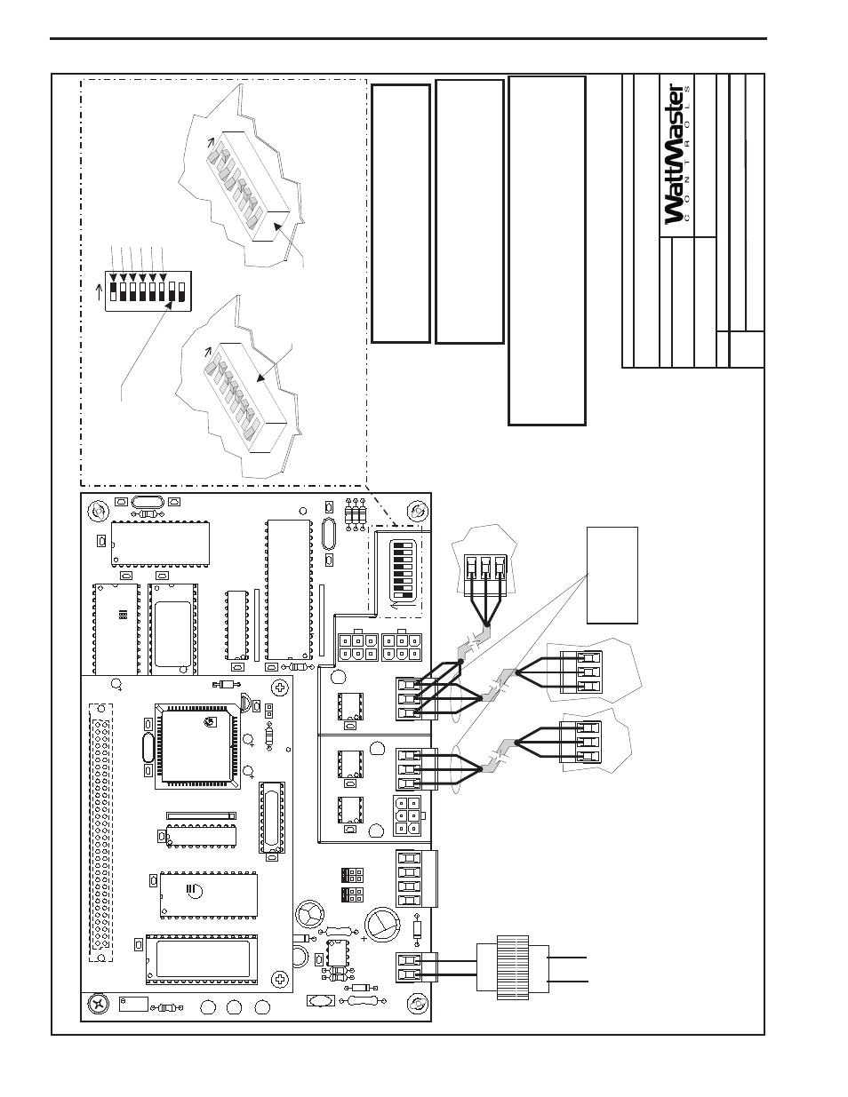
Component & System Wiring
46
Notes:
1.)
All
W
iring
T
o
Be
In
Accordance
With
Local
And
N
ational
Electrical
C
odes
And
S
pecifications.
2.)
All
C
ommunication
Wiring
T
o
Be
2
C
onductor
T
w
isted
P
air
With
Shield.
Use
B
elden
#82760
Or
Equivalent.
Component
W
iring
D
iagram
03/24/04
V
A
V
-MiniLinkPolDevW
r1A.CDR
MiniLink
Polling
D
evice
1o
f1
MiniLink
Polling
D
evice
CommLink
T
erminals
Only
First
MiniLink
PD
T
o
Be
Connected
T
o
CommLink,
Otherwise
Connect
MiniLink
PD
T
o
Network
T
erminals
Of
Previous
Or
Next
MiniLink
PD
On
Loop
24
V
A
C
Class
2
T
ransformer
Rated
For
6
V
A
Load
Minimum
Not
Used
T
o
WMV
A
V
Controller
T
erminals
MiniLink
P
D
Network
T
erminals
Connect
MiniLink
PD
T
o
Network
T
erminals
Of
Previous
Or
Next
MiniLink
PD
On
Loop.
EPROM
U3
U5
RAM
CX2
1
U2
R1
C3
U4
CX3
CX4
YS101818P552
PROCESSORPBOARD
CX5
C1
U1
R2
CX1
CX6
WDOG
U6
PHILIPS
D1
P1
X1
C2
C4
0-10V
4-20mA
THERM
R27
R31
D4
GND
GND
24VAC
24VAC
TB1
D5
C1
1
U12
LED
2
POWER
V1
R25
R26
C7
CX15
CX13
PROC.
DRIVER
LOOP
DRIVER
LOCAL
LOOP
GND
AIN2
AIN1
+5V
TB2
P4
OFF=0-5V
AIN2
AIN1
0-10V
4-20mA
THERM
TB3
U15
LD5
LD6
U13
C8
LED
1
RV
1
R4
VREF
CX2
U1
1
YS101900PMINILINK
POLLING
DEVICE
REV
.
1
OFF
1
2
4
8
16
32
CX14
NETWORK
DRIVER
RN3
SHLD
SHLD
SHLD
SHLD
T
T
G
T
T
T
TB4
R
R
485
LOOP
R
R
R
U14
NETWORK
LOOP
P5
ADD
P3
R24
LD4
C9
U10
RN2
SW1
R30
X2
R29
R28
C10
U6
CX6
CX1
U7
U1
X1
C3
C1
R3
CX7
Line
V
olt
age
16
32
8
4
2
1
Address
Switch
Shown
Is
Set
For
Address
1
Address
Switch
Shown
Is
Set
For
A
ddress
13
Controller
Address
Switch
This
Switch
Should
Be
In
The
OFF
Position
As
Shown
Note:
The
Power
T
o
The
MiniLink
PD
Must
Be
Removed
A
nd
Reconnected
Af
ter
Changing
The
Address
Switch
Settings
In
Order
For
Any
C
hanges
T
o
T
ake
Ef
fect.
Caution
Disconnect
All
Communication
Loop
Wiring
F
rom
The
MiniLink
PD
Before
Removing
Power
From
The
MiniLink
PD.
Reconnect
Power
And
Then
Reconnect
Communication
Loop
Wiring.
ADD
ADD
ADD
The
Address
For
Each
MiniLink
PD
Must
Be
Unique
T
o
The
Other
MiniLink
PDs
On
The
Local
Loop
And
B
e
Between
1
and
60
FILENAME
DA
TE:
B.
Crews
DESCRIPTION:
P
AGE
DRA
WN
BY
:
JOB
NAME
Communication
Wiring
T
o
Be
Wired
T
to
T
,
SHLD
(G)
to
SHLD
(G)
&
R
to
R
3.)
All
C
ommunication
W
iring
T
o
Be
2
C
onductor
T
w
isted
Pair
W
ith
Shield.
Use
Belden
#82760
Or
Equivalent.
MiniLink Polling Device Wiring Using Wire Terminals