3 relay output expansion board wiring (cont’d), Component & system wiring 38, Component wiring diagram – WattMaster VAV User Manual
Page 38: Job name, 2 of 3, Fan relay, 24vac com
Component & System Wiring
38
Notes:
FILENAME
DATE:
B. Crews
DESCRIPTION:
PAGE
DRAWN BY:
Component Wiring Diagram
JOB NAME
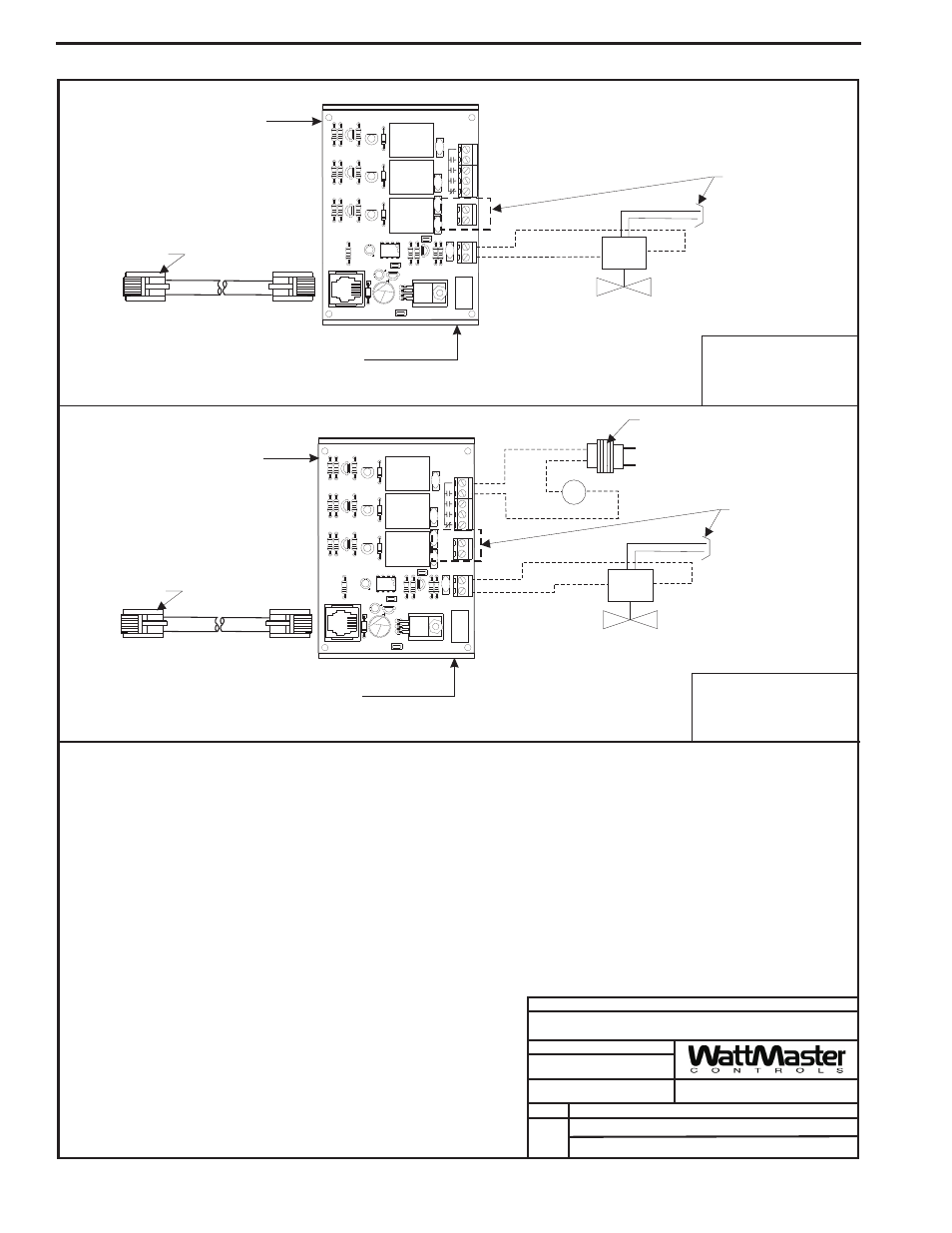
Typical Wiring For
Single Duct Terminal
With Modulating Hot
Water Heat
Typical Wiring For
Fan Terminal Unit
With Modulating
Hot Water Heat
OE322 - 3 Relay -1 Analog Output Board
2 of 3
WattMaster Part # BK000047
Snaptrack Supplied by WattMaster
Mounted by Others. Remove Control
Board from Snaptrack & Mount Snaptrack on Box
WattMaster Part # BK000047
Snaptrack Supplied by WattMaster
Mounted by Others. Remove Control
Board from Snaptrack & Mount Snaptrack on Box
WattMaster Part #OE322
Relay Expansion Board
w/ Modular Cable
Supplied by WattMaster
Mounted & Wired by Others
WattMaster Part #OE322
Relay Expansion Board
w/ Modular Cable
Supplied by WattMaster
Mounted & Wired by Others
Q3
R6
R3
R10
Q2
R9
R5
R2
Q1
R8
R4
R1
R7
D1
PJ1
C2
C4
VR2
C6
C1
U1
RLY
3
D2
2
RLY
D3
1
RLY
D4
K1
2RAOUT BD.
YS101714
REV. 3
V4
V3
K2
K3
V1
C5
R12
R11
R13
VR1
R14
TB1 GND
OUT
V5
+
ANALOG
+V
GND
TB3
3
COM
1
2
TB2
LM358
C3
V2
7824CT
M
I
O
SERIAL
#
Q4
24 VAC Transformer Supplied &
Wired by Others. Size For Required
Fan Relay Load.
24VAC
COM
Fan Relay
24 VAC Fan Relay Supplied and
Installed by Others. 2 Amp Max.
Load For Fan Relay.
R1
HWV
HWV
0-10 VDC Modulating
Hot Water Valve Supplied & Installed by Others
0-10 VDC Modulating
Hot Water Valve Supplied & Installed by Others
0-10 VDC Signal
0-10 VDC Signal
Supply Power
Of Required Voltage
To Valve Motor
(By Others)
24 VDC Power Only
(12 Watts Max.)
Is Available From TB3
Terminals (+V & GND)
Supply Power
Of Required Voltage
To Valve Motor
(By Others)
24 VDC Power Only
(12 Watts Max.)
Is Available From TB3
Terminals (+V & GND)
Q3
R6
R3
R10
Q2
R9
R5
R2
Q1
R8
R4
R1
R7
D1
PJ1
C2
C4
VR2
C6
C1
U1
RLY
3
D2
2
RLY
D3
1
RLY
D4
K1
2RAOUT BD.
YS101714
REV. 3
V4
V3
K2
K3
V1
C5
R12
R11
R13
VR1
R14
TB1 GND
OUT
V5
+
ANALOG
+V
GND
TB3
3
COM
1
2
TB2
LM358
C3
V2
7824CT
M
I
O
SERIAL
#
Q4
09/26/06
1.) All Wiring to be in Accordance With Local & National Electrical Codes
& Specifications.
Connect To VAVBOX Controller
Using Modular Cable Supplied
By WattMaster
Connect To VAVBOX Controller
Using Modular Cable Supplied
By WattMaster
VAV-OE322-3RELAY1OUTBD.CDR
3 Relay Output Expansion Board Wiring (Cont’d)