Vavbox controller wiring, Component & system wiring 36, Vavbox controller – WattMaster VAV User Manual
Page 36: Wattmaster vav system, Address add address add, Filename date: b. crews description: page drawn by, Address add, Shield r t, 1 of 1
Component & System Wiring
36
C
O
N
T
R
O
L
S
FILENAME
DATE:
B. CREWS
DESCRIPTION:
PAGE
DRAWN BY:
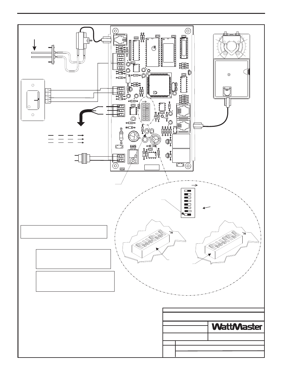
VAVBOX Controller
See Note 1
R
SH
T
R
SH
T
R
SH
T
R
SH
T
All Comm Loop Wiring Is
Straight Thru
Required VA For Transformer
Each VAVBOX Controller = 6 VA Min.
(Includes Actuator)
24VAC
GND
GND
AUX
TMP
NORMAL
OVR
R
E
L
O
C
R
E
M
R
O
A
W
16
32
TOKEN
NET
8
4
2
1
Caution!
VAVBOX Controllers Must Have Address Switches Set
Between 1 And 58
Room Sensor
Diagnostic Blink Code LED
VAVBOX Damper Actuator
Local Loop
RS-485
9600 Baud
Airflow Sensor (Optional)
Only Used For Pressure
Independent Applications
Connect To
Next VAVBOX
Controller
And/Or WMVAV
Controller On
Local Loop
Address Switch Shown Is
Set For Address 9
Address Switch Shown Is
Set For Address 13
Controller
Address Switch
This Switch Must Be
In The ON Position
As Shown
Switches Labeled 32 And
Token Should Be In The
OFF Position As Shown
Note:
The Power To The VAVBOX Controller Must Be
Removed And Reconnected After Changing The
Address Switch Settings In Order For Any Changes
To Take Effect.
Caution:
Disconnect All Communication Loop Wiring
From The VAVBOX Controller Before Removing Power
From The VAVBOX Controller. Reconnect Power And
Then Reconnect Communication Loop Wiring.
ADDRESS
ADD
ADDRESS
ADD
ADDRESS
ADD
Connection To AUX
Terminal Required Only
When Sensor Is Specified
With Slide Adjust Option
JOB NAME
05/12/04
VAV-VAVBOXWire1.CDR
WattMaster VAV System
1
0
SHIELD
R
T
Hi
Lo
Airflow
Notes:
3.)The Supply Air Sensor is not required when the VAVBOX Controllers are
connected with WMVAV Unit Controller boards. A global supply air
temperature is broadcast by the one of the WMVAV Unit Controllers. The
Supply Air Sensor is only required if the VAVBOX Controller is required to
operate as a “Stand Alone” controller.
1.) All wiring to be in accordance with local and national electrical codes
and specifications.
2.) All communication wiring to be 2 conductor twisted pair with shield.
Use Belden #82760 or equivalent.
The Address For Each Controller
Must Be Between 1 And 58 And Be
Unique To The Other Controllers
On The Local Loop
1 of 1
(See Note 3)
CX4
R28
R24
7824
GND
R17
R16
U7
POWER
R26
YS101562
REV
.
3
24VAC
D4
VR1
L1
C7
D3
SCAN
R21
REC
C6
R14
CX10
U1
1
COMM
C15
R25
SW1
U10
16
32
TOKEN
NET
4
8
2
1
U6
ADDRESS
EWDOG
C1
1
R20
R19
ADD
VREF
ADJ
T'STAT
R32
D6
C14
C13
R27
C8
R23
C10
P.U.
R22
CX9
C9
U9
U8
D5
RN1
AIRFLOW
R34
R18
CX8
U4
R15
Q3
D2
K2
V2
PJ2
R100
R12
R1
1
Q2
D1
K1
R9
R13
V1
ACTUA
T
O
R
C4
R8
CX6
C5
C3
PJ1
CX5
R6
R7
R5
R4
C2
EXP
ANSION
CX2
PA
L
X1
C1
EPROM
R1
R2
R3
U2
Q1
CX1
U3
CX3
U1
P.U.
O
I
D7
R33
U5
P.U.
485
DR
V
C16
V3
R35
PJ3
OFF
VAVBOX Controller Wiring