Wmvav controller addressing, Component & system wiring 19, Gnd 24vac – WattMaster VAV User Manual
Page 19: Expansion pressure sensor, Address add address add
Component & System Wiring
19
WMVAV Controller Addressing
FILENAME
DATE:
B. Crews
DESCRIPTION:
PAGE
DRAWN BY:
Component Wiring Diagram
JOB NAME
2 of 2
4
NETWORK
TOKEN
16
32
8
SW1
ADD
2
1
ADDRESS
V6
POWER
GND
24VAC
L1
D16
R6
C9
SC1
R1
1
U1
1
D13
C16
VR2
TB4
R27
C13
R10
VR1
C19
C18
R7
D10
R13
D12
C7
CX10
U10
CX12
U12
U14
CX14
PJ3
PJ2
PJ1
EXPANSION
PRESSURE
SENSOR
C17
D15
R26
C20
R25
R24
R22
U15
CX13
U13
C15
R19
R15
C14
D18
D17
PU1
PU2
PU3
PU4
PU5
PU7
D6
D7
D8
D9
D11
D14
C12
C10
0-5
VDC
0-1
VDC
JP1
C1
1
X2
GND
TB3
INPUTS
GND
GND
+VDC
AIN1
AIN2
AIN3
AIN4
AIN5
AOUT1
AOUT2
AIN7
RN5
D19
CX15
16
32
TOKEN
NETWORK
8
4
2
1
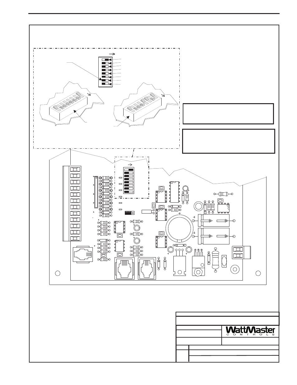
Address Switch Shown Is
Set For Address 1
Address Switch Shown Is
Set For Address 13
Controller
Address Switch
This Switch Should Be
In The OFF Position
As Shown
Note:
The Power To The Controller Must Be Removed And
Reconnected After Changing The Address Switch
Settings In Order For Any Changes To Take Effect.
Caution
Disconnect All Communication Loop Wiring From The
Controller Before Removing Power From The Controller.
Reconnect Power And Then Reconnect Communication
Loop Wiring.
ADDRESS
ADD
ADDRESS
ADD
ADDRESS
ADD
The Address For Each Controller
Must Be Unique To The Other Controllers
On The Local Loop And Be Between 1 and 59
WMVAV Controller
05/12/04
VAV-WMVAVWIR1A.CDR