4 relay output expansion board wiring, Component & system wiring 33, 4 relay output expansion board – WattMaster VAV User Manual
Page 33: Pilot duty relays (by others)
Component & System Wiring
33
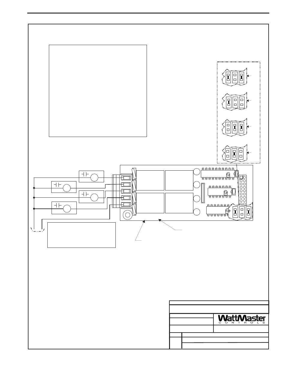
Notes:
1.)All Wiring To Be In Accordance With
Local And National Electrical Codes
and Specifications.
FILENAME
DATE:
B. Crews
DESCRIPTION:
PAGE
DRAWN BY:
Component Wiring Diagram
JOB NAME
05/12/04
VAV-OE357-4RELAYOUT.CDR
OE357 4 Relay Output Expansion Board
1 of 1
Relay Output Dry Contacts
R6 Through R21 May Be User Configured For The
Following:
Not Used
Heating (Aux. Heating)Stages
Cooling (Compressor) Stages
Warm-up Mode Command For Boxes
Reversing Valve (Air To Air Heat Pumps)
Gas Reheat Control For Dehumidification
Exhaust Fan Interlock
Preheat Coil
Configure Relays By Utilizing The System Manager,
Modular Service Tool or Prism Computer Front End
Software.
Alarm Relay
Override
Occupied
Economizer
4 Relay Output Expansion Board
UL5A250V
AC
G5L-114P
-PS
OMRON
CONTACT
:
24VDC
UL5A250V
AC
G5L-114P
-PS
OMRON
CONTACT
:
24VDC
UL5A250V
AC
G5L-114P
-PS
OMRON
CONTACT
:
24VDC
UL5A250V
AC
G5L-114P
-PS
OMRON
CONTACT
:
24VDC
K3
K2
4RLY IO BD.
4RLY IO BD.
V4
K4
YS101790
TB1
V1
K1
K3
U2
K4
RN1
PCF8574P
U3
CX3
U1
ULN2803A/
ULN2803A/
K2
K1
74HC04N
P1
CX2
CX1
Relays 6-9
Relays 10-13
Relays 14-17
Relays 18-21
Address Jumpers
Located On Base
Board Under
Expansion Board
Typical Wiring For Relay
Outputs - 6 Through 21
R1
R2
R3
R4
24Volt
Power
Mount Expansion Board To Either The OE352 2 Slot
Or OE353 4 Slot Expansion Base Board
Note:
All Circuit Board Contacts Are N.O.
All Contacts Are Rated For 2 Amps @
24VAC Pilot Duty Only
Do Not Apply Any Voltage Greater Than
24VAC
!
!
!
Pilot Duty Relays
(By Others)
Edge
of
Base
Board
Edge
o
f
Base
Board
Edge
o
f
Base
B
oard
Edge
of
Base
Board
4 Relay Output Expansion Board Wiring