Midplane, Chapter 1 about the pfc500/e – Grass Valley PFR 500/E Dec 10 2001 User Manual
Page 20
Chapter 1 About the PFC500/E
20
PFC500/E Instruction Manual
November 17, 2000
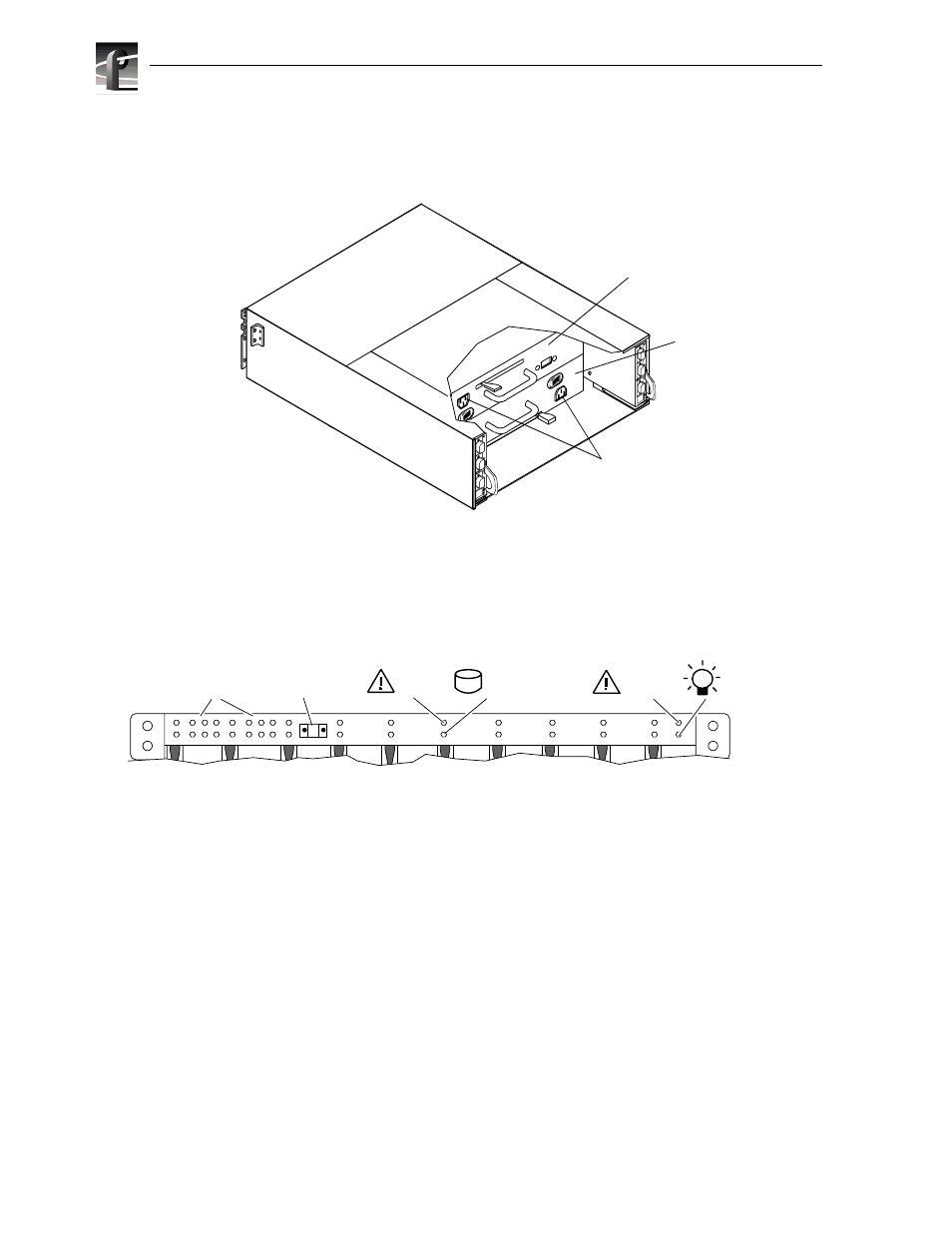
The front panel contains the chassis address (CA) light, two status lights for each disk
module slot, and two status lights. All lights are visible with the front door closed.
The chassis address light displays the chassis address setting for the PFC 500. The
PFC500 must have a CA of 0. You must set that CA using the chassis address
switches, as explained in Chapter 2.
The status lights are described in the “Monitoring PFC500/E status” on page 42.
Midplane
The midplane distributes power and signals to all the chassis components. All CRUs
except the fan packs plug directly into midplane connectors.
A
B
E
X
P
A
B
E
X
P
Power cord
connectors
Power supply
in slot A
Power supply
in slot B
0
1
2
3
4
5
1
0
6
7
8
9
10
11
2
3
4
5
6
7
8
9
Chassis
address lights
PFC 500/E status lights
Disk module status lights
(two per module)
System
Check
Power
Disk
check
0
Disk
Active
Chassis
address switch
(not visible with
door closed)