Setting addresses and connecting cables – Grass Valley PFR 500/E Dec 10 2001 User Manual
Page 35
Setting addresses and connecting cables
November 17, 2000
PFC 500/E Instruction Manual
35
Setting addresses and connecting cables
You must now set FC-AL address ID on the RAID controllers, set the chassis ID,
connect Fibre Channel cables, and connect power cables. Refer to the Profile XP System
Guide for the settings required for your installation.
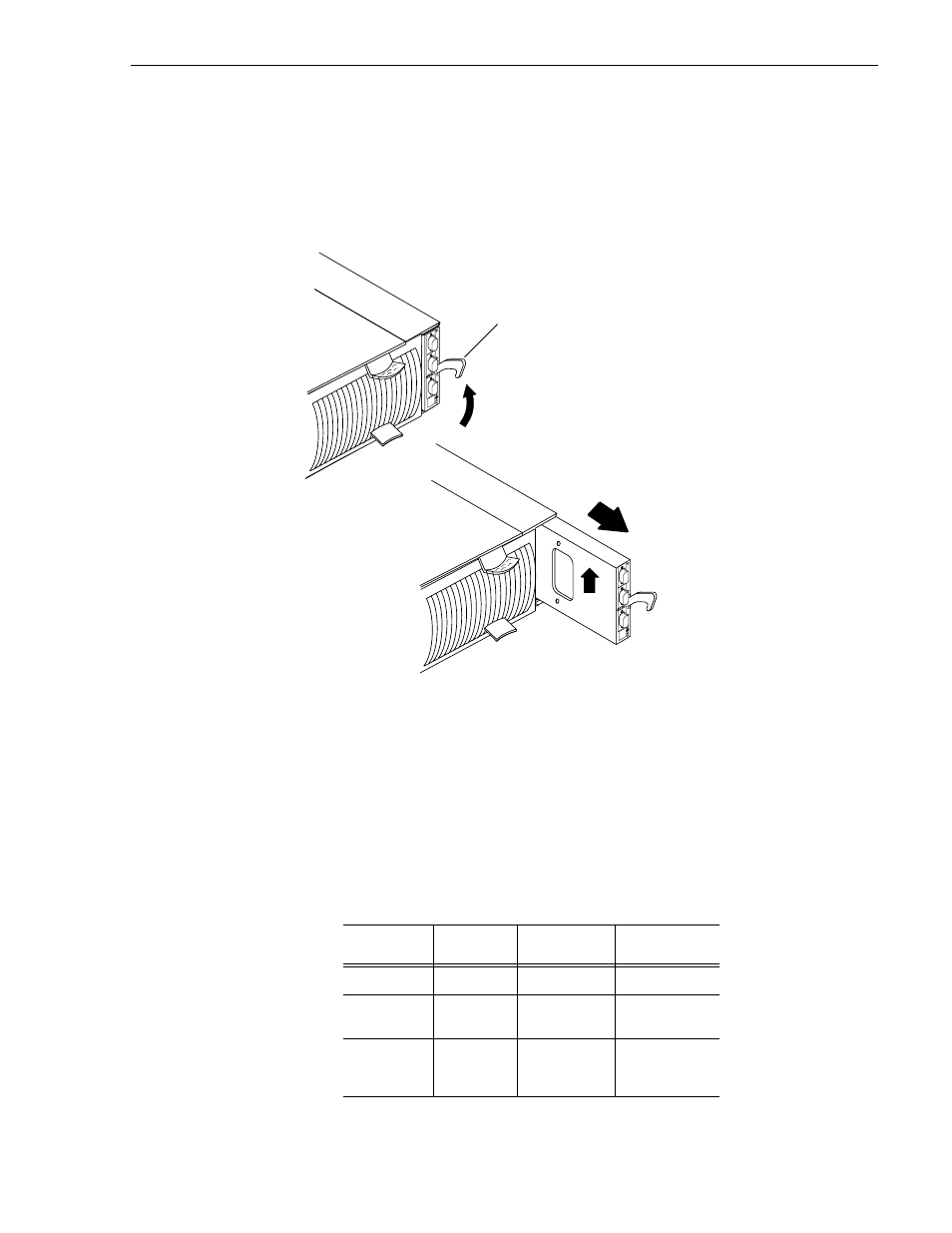
1. At the back of the PFC500 chassis, remove each RC from its slot as shown below.
2. For each RC, set the FC-AL address ID using the FC-AL ID switches on the RC
printed circuit board.
Each node (such as an RC) on a Fibre Channel front-end loop must have a unique
FC-AL address ID. The FC-AL protocol translates the FC-AL address ID into an
8-bit arbitrated loop physical address (ALPA).
IMPORTANT: Each RC’s FC-AL ID must be unique from all other FC devices on
that same FC-AL loop.
When using redundant RCs, set the FC-AL ID on the RCs for all PFC 500s
connected as indicated in the following table.
Number of
PFC500s
PFC 500
chassis
Primary RC’s
FC-AL ID
Redundant
RC’s FC-AL ID
1
First
0
1
2
First
Second
0
1
2
3
3
First
Second|
Third
0
1
2
3
4
5
A
B
EXP
A
B
EXP
Latch up
A. Pull up the latch on the RC.
B. Grasp the RC and gently
pull it out of the slot