Circle and circular arcs, Yx z dr– dr+ y x z – HEIDENHAIN TNC 360 User Manual User Manual
Page 98
TNC 360
5-14
5
Programming Tool Movements
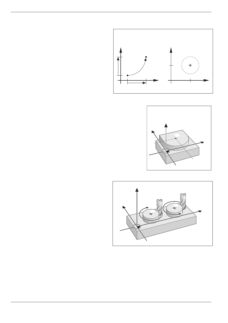
Fig. 5-17:
Circular arc and circle center
Fig. 5.18:
Circle center coordinates
Fig. 5.19:
Direction of rotation for circular movements
5.4
Path Contours – Cartesian Coordinates
CC
CC
Y
X
Z
DR–
DR+
Y
X
Z
Y
CC
CC
X
CC
Y
X
Y
X
Y
CC
CC
X
CC
Circle and circular arcs
The TNC can control two machine axes simultane-
ously to move the tool in a circular path.
Circle Center CC
You can define a circular movement by entering its
center CC.
A circle center can also serve as reference (pole) for
polar coordinates.
Direction of Rotation DR
When there is no tangential transition to another
contour element, enter the mathematical direction
of rotation DR, where
• a clockwise direction of rotation is mathematical-
ly negative: DR-
• a counterclockwise direction of rotation is
mathematically positive: DR+