Cycle parameters, 2 centering (cy c le 240) – HEIDENHAIN TNC 128 (77184x-01) User Manual
Page 388
388
Drilling, boring and thread cycles
16.2 CENTERING (Cy
c
le 240)
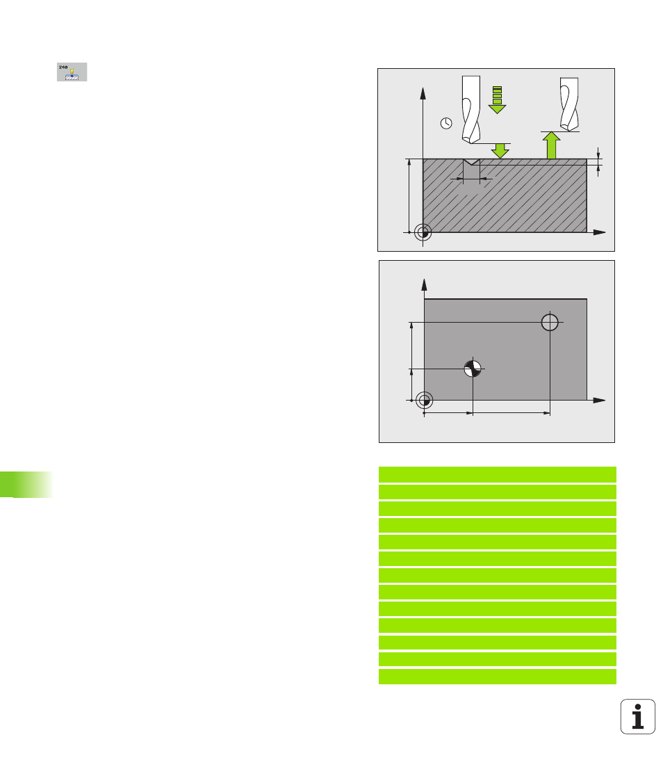
Cycle parameters
Set-up clearance Q200 (incremental): Distance
between tool tip and workpiece surface. Enter a
positive value. Input range 0 to 99999.9999
Select depth/diameter (0/1) Q343: Select whether
centering is based on the entered diameter or depth.
If the TNC is to center based on the entered diameter,
the point angle of the tool must be defined in the
T-ANGLE column of the tool table TOOL.T.
0: Centering based on the entered depth
1: Centering based on the entered diameter
Depth Q201 (incremental): Distance between
workpiece surface and centering bottom (tip of
centering taper). Only effective if Q343=0 is defined.
Input range -99999.9999 to 99999.9999
Diameter (algebraic sign) Q344: Centering diameter.
Only effective if Q343=1 is defined. Input range
-99999.9999 to 99999.9999
Feed rate for plunging Q206: Traversing speed of
the tool during centering in mm/min. Input range: 0 to
99999.999; alternatively FAUTO, FU
Dwell time at depth Q211: Time in seconds that the
tool remains at the hole bottom. Input range 0 to
3600.0000
Coordinate of workpiece surface Q203 (absolute):
Coordinate of the workpiece surface. Input range
-99999.9999 to 99999.9999
2nd set-up clearance Q204 (incremental): Coordinate
in the spindle axis at which no collision between tool
and workpiece (fixtures) can occur. Input range 0 to
99999.9999
Example: NC blocks
11 CYCL DEF 240 CENTERING
Q200=2
;SET-UP CLEARANCE
Q343=1
;SELECT DEPTH/DIA.
Q201=+0
;DEPTH
Q344=–9
;DIAMETER
Q206=250
;FEED RATE FOR PLNGNG
Q211=0.1
;DWELL TIME AT DEPTH
Q203=+20
;SURFACE COORDINATE
Q204=100
;2ND SET-UP CLEARANCE
12
X+30 R0 FMAX
13
Y+20 R0 FMAX M3 M99
14
X+80 R0 FMAX
15
Y+50 R0 FMAX M99
X
Z
Q200
Q344
Q206
Q210
Q203
Q204
Q201
30
X
Y
20
80
50