5 installation procedure – Yaskawa 1000 Series Drive Option - CC-Link Installation User Manual
Page 17
5 Installation Procedure
YASKAWA ELECTRIC TOBP C730600 44A YASKAWA AC Drive-Option Card CC-Link Installation Manual
17
Figure 4 Installing the Option
3.
Wire the CC-Link Option to the terminal block on the CC-Link Option.
For wiring instructions, see
.
For exposed cables in drives 2A004 to 0069, 4A0002 to 0044, use a pair of wire
cutters to create an opening on the left side of the front cover that allows wiring to
pass through. Sharp edges along the opening that was created should be smoothed
down with a file or sand paper so prevent any damage to the wires.
Drives 2A0081 to 0021, 4A0058 to 0165 have enough space to keep all wiring
inside the unit.
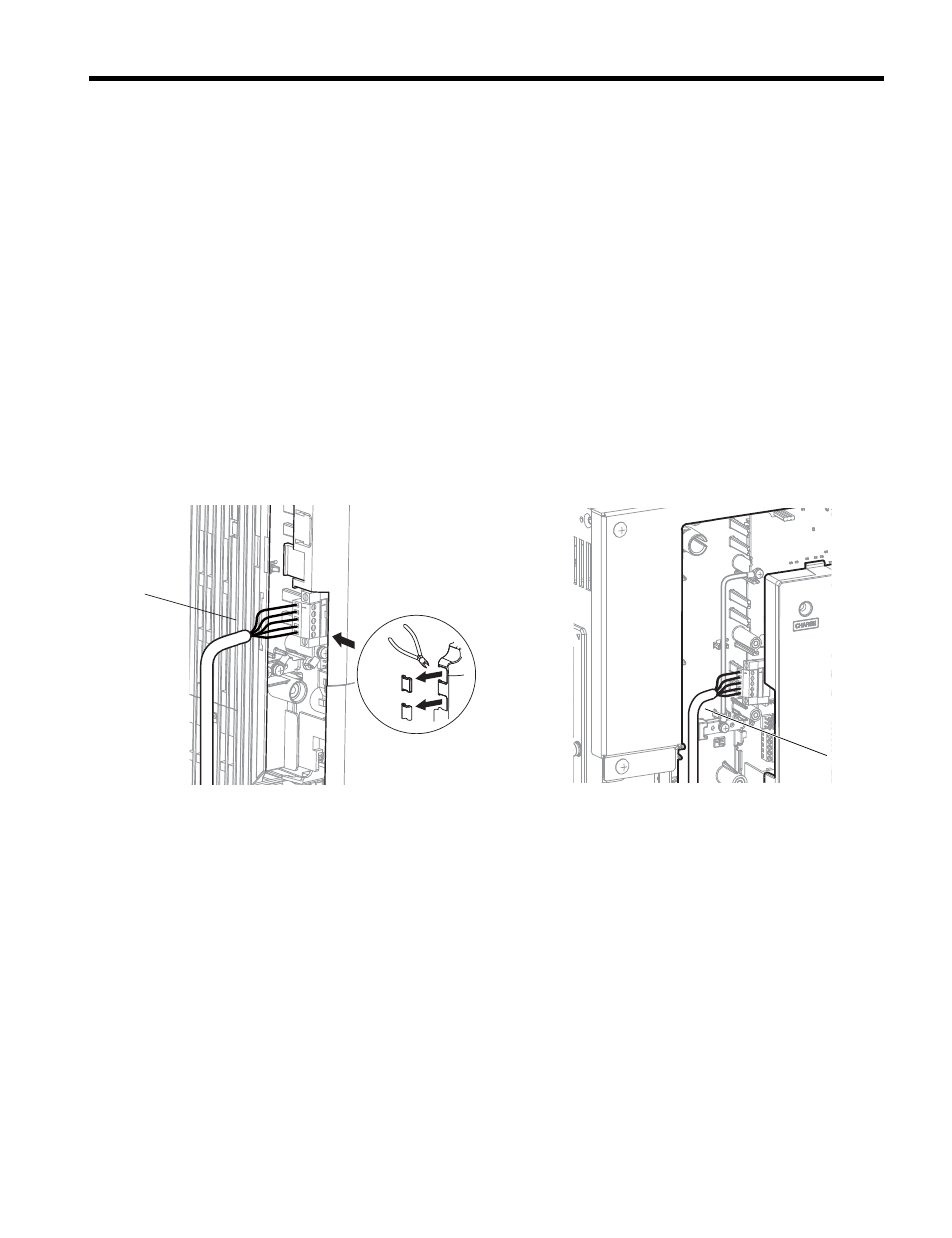
Figure 5
Figure 5 Wiring space
4.
Place the front cover back onto the drive as it was before.
Note: 1. Take care when wiring the CC-Link Option so that the front cover easily fits back onto the drive.
2. Install Cable Cover option to maintain the drive Enclosure Type.
5.
Attach the LED label packaged with the option card as shwn in
A – Connector CN5-C
G – Lead line
B – Connector CN5-B
H – Use wire cutters to create an
opening for cable lines
C – Connector CN5-A
I – Operator
D – Drive grounding terminal (FE)
J – LED label
E – Insert connector CN5 here
K – Front cover
F – CC-Link Option
A – Cable through hole
(2A0004 to 0069, 4A0002 to 0044)
B – Space for wiring
(2A0081 to 0021, 4A0058 to 0165)
B
A