5 installation procedure – Yaskawa 1000 Series Drive Option - CC-Link Installation User Manual
Page 19
5 Installation Procedure
YASKAWA ELECTRIC TOBP C730600 44A YASKAWA AC Drive-Option Card CC-Link Installation Manual
19
■
Communication Cable Specifications
Use only CC-Link dedicated communication cable; the Yaskawa warranty does not cover
other cable types. For more information on cables, refer to the CC-Link website at http://
www.cc-link.org/.
■
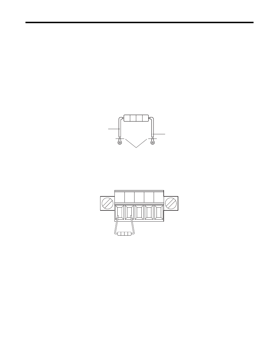
Terminal Resistor Connection
When the CC-Link Option is the last station connected in a CC-Link network, the terminal
resistor needs to be set to that CC-Link Option. Follow the instructions below.
1.
Cut the terminal resistor tube as shown.
Note: For the terminal resistor, either use what is already built into the master unit, or use a standard-
market resistor of 110
Ω, ±5% (1/2 W).
Figure 8
Figure 8 Terminal Resistor
2.
Loosen the attachment screw and insert the terminal resistor described in the first
step between terminals DA and DB.
Figure 9
Figure 9 Terminal Resistor Wiring
jumper
cut here
cut
DA DB DG SLD SLD