4 option components, Si-ep3 profinet option, 4option components – Yaskawa SI-EP3 PROFINET Installation User Manual
Page 10
Advertising
10
YASKAWA TOEP YEACOM 07A 1000-Series Option PROFINET SI-EP3 Installation Manual
4 Option Components
4
Option Components
◆
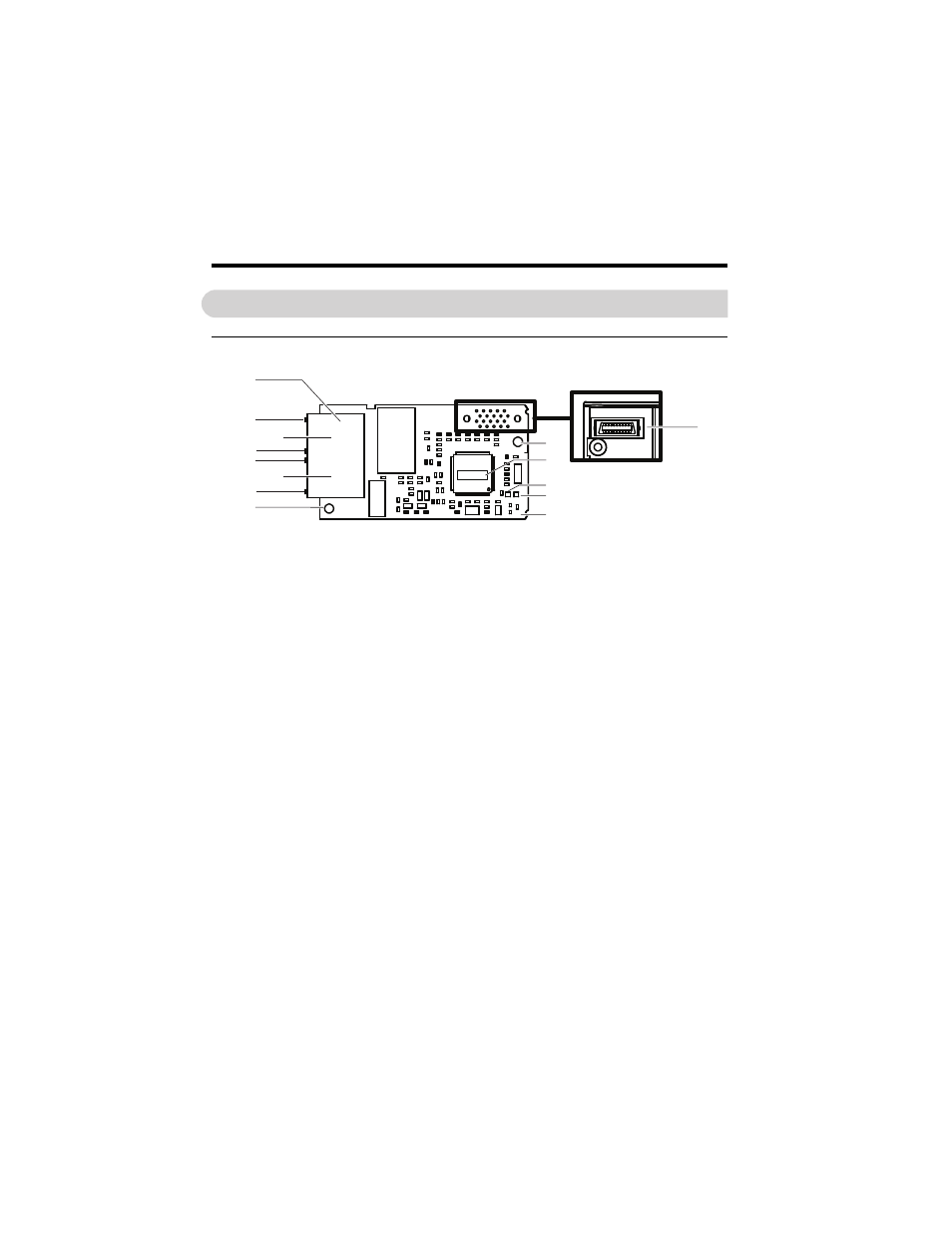
SI-EP3 PROFINET Option
Figure 1
Figure 1 Option (Top View)
A – Ground Terminal and installation hole
H – PROFINET cable connection
B – CN1 Port 2 LED (10/100)
<1> The ground wire provided in the option shipping package must be connected during installation.
I – Option connector CN5
C – CN1 Port 2
J – Installation hole
D – CN1 Port 2 LED (LINK/ACT)
K – SI-EP3 Firmware Label
VST-
E – CN1 Port 1 LED (10/100)
L – LED (NS)
F – CN1 Port 1
M – LED (MS)
G – CN1 Port 1 LED (LINK/ACT)
<2>
Refer to Option LED Display on page 12
for details on the LEDs.
N – PROFINET PCB
N
A
I
H
G
E
B
D
F
C
J
L
K
M
Underside
Advertising
This manual is related to the following products: