2 spindle orientation – Yaskawa A1000 AC Drive Spindle Orientation User Manual
Page 10
2 Spindle Orientation
10
YASKAWA TM.A1000SW.063 Spindle Orientation A1000 Custom Software Supplement
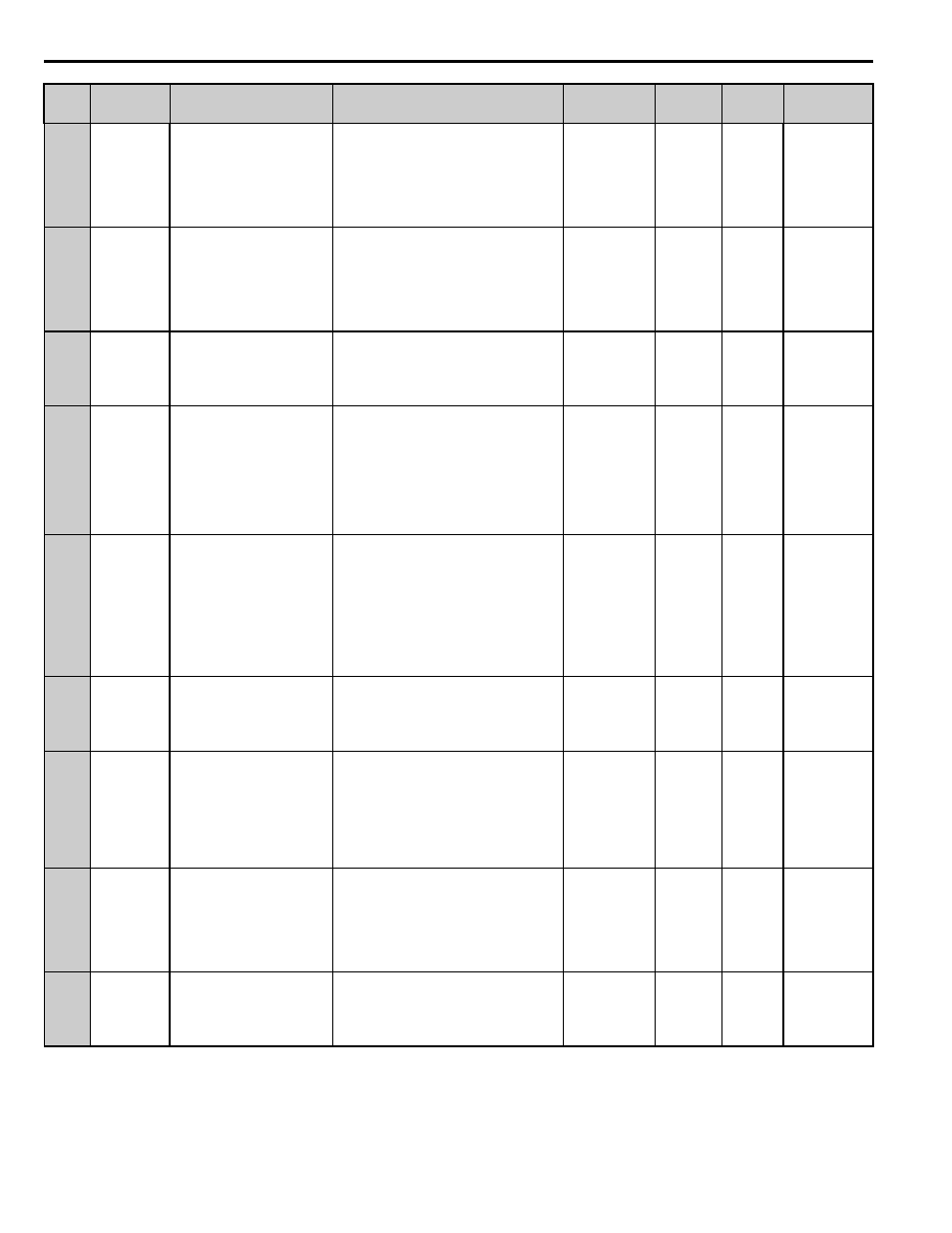
S2-05
695h
High Frequency Slip
Compensation Gain
HF SlipComp Gain
Sets the gain for the Motor Slip Compensation at
Hi-Speed Function. Although this parameter rarely
needs to be changed, adjustments might be needed
under the following circumstances:
If the motor at constant speed is slower than the
frequency reference, increase S2-05.
If the motor at constant speed is faster than the
frequency reference, decrease S2-05.
0.0 to 2.5
0.0
Yes
– – – Y– – N
S2-06
696h
High Frequency Slip
Compensation Primary Delay Time
HF SlipComp Time
Sets the filter on the output side of the Slip
Compensation at Hi-Speed Function. Although this
parameter rarely needs to be changed, adjustments
might be needed under the following
circumstances:
-Decrease the setting when the slip compensation
response is too slow.
-Increase this setting when speed is unstable.
0 to 10000 ms
2000
Yes
– – – Y– – N
S2-07
697h
High Frequency Slip
Compensation Limit
HF SlipComp Lim
Sets the upper limit for the Slip Compensation at
Hi-Speed Function as a percentage of the motor
rated slip (E2-02).
0 to 250%
200
No
– – – Y– – N
S2-08
698h
High Frequency Slip
Compensation Selection During
Regeneration
HF SlipCompRegen
When Slip Compensation during Regeneration at
Hi-Speed is activated and a regenerative load is
applied, it might be necessary to use a dynamic
braking option (braking resistor, braking resistor
unit, or braking unit).
0: Disabled
1: Enabled (6 Hz and Above)
2: Enabled
(Compensation provided wherever possible)
0 to 2
0
No
– – – Y– – N
S2-11
699h
Motor 2 Control Mode Switchover
Frequency
HF SwOver Freq 2
Sets the frequency of switching from Closed Loop
Vector Control to V/f Control for Motor 2
This function is disabled when 0 or 400Hz is set,
the inverter runs as V/f Control when 0 is set, and
Closed Loop Vector Control when 400Hz is set.
However, OPE21 occurs when the relations among
Control Mode Switch Frequency (S2-11) and PG
Pulse per Revolution (F1-31) and Numbers of
Motor Poles (E4-04) are set higher than the
permissible input frequency of PG option.
0 to 400 Hz
400
No
– – – Y– – N
S2-12
69Ah
Motor 2 Control Mode Switchover
Bandwidth
HF CtrlModeSwBW2
Sets the hysteresis width of Control Mode Switch
for Motor 2.
Increase if shock occurs during Control Mode
switching.
2 to 100 Hz
20
No
– – – Y– – N
S2-15
69Dh
Motor 2 High Frequency Slip
Compensation Gain
HF SlipCompGain2
Sets the gain for the Motor Slip Compensation at
Hi-Speed Function for Motor 2. Although this
parameter rarely needs to be changed, adjustments
might be needed under the following
circumstances:
-If the motor at constant speed is slower than the
frequency reference, increase S2-15.
-If the motor at constant speed is faster than the
frequency reference, decrease S2-15.
0.0 to 2.5
0.0
Yes
– – – Y– – N
S2-16
69Eh
Motor 2 High Frequency Slip
Compensation Primary Delay Time
HF SlipCompTime2
Sets the filter on the output side of the Slip
Compensation at Hi-Speed Function for Motor 2.
Although this parameter rarely needs to be
changed, adjustments might be needed under the
following circumstances:
-Decrease the setting when the slip compensation
response is too slow.
-Increase this setting when speed is unstable.
0 to 10000 ms
2000
Yes
– – – Y– – N
S2-17
69Fh
Motor 2 High Frequency Slip
Compensation Limit
HF SlipComp Lim2
Sets the upper limit for the Slip Compensation at
Hi-Speed Function for Motor 2 as a percentage of
the motor rated slip (E4-02).
0 to 250%
200
No
– – – Y– – N
No.
MEMOBUS/
Modbus
Address
Name
Digital Operator Display
Description
Range
Default
Value
Change
During
Run
Control Method/
Access Level