2 spindle orientation – Yaskawa A1000 AC Drive Spindle Orientation User Manual
Page 13
2 Spindle Orientation
YASKAWA TM.A1000SW.063 Spindle Orientation A1000 Custom Software Supplement
13
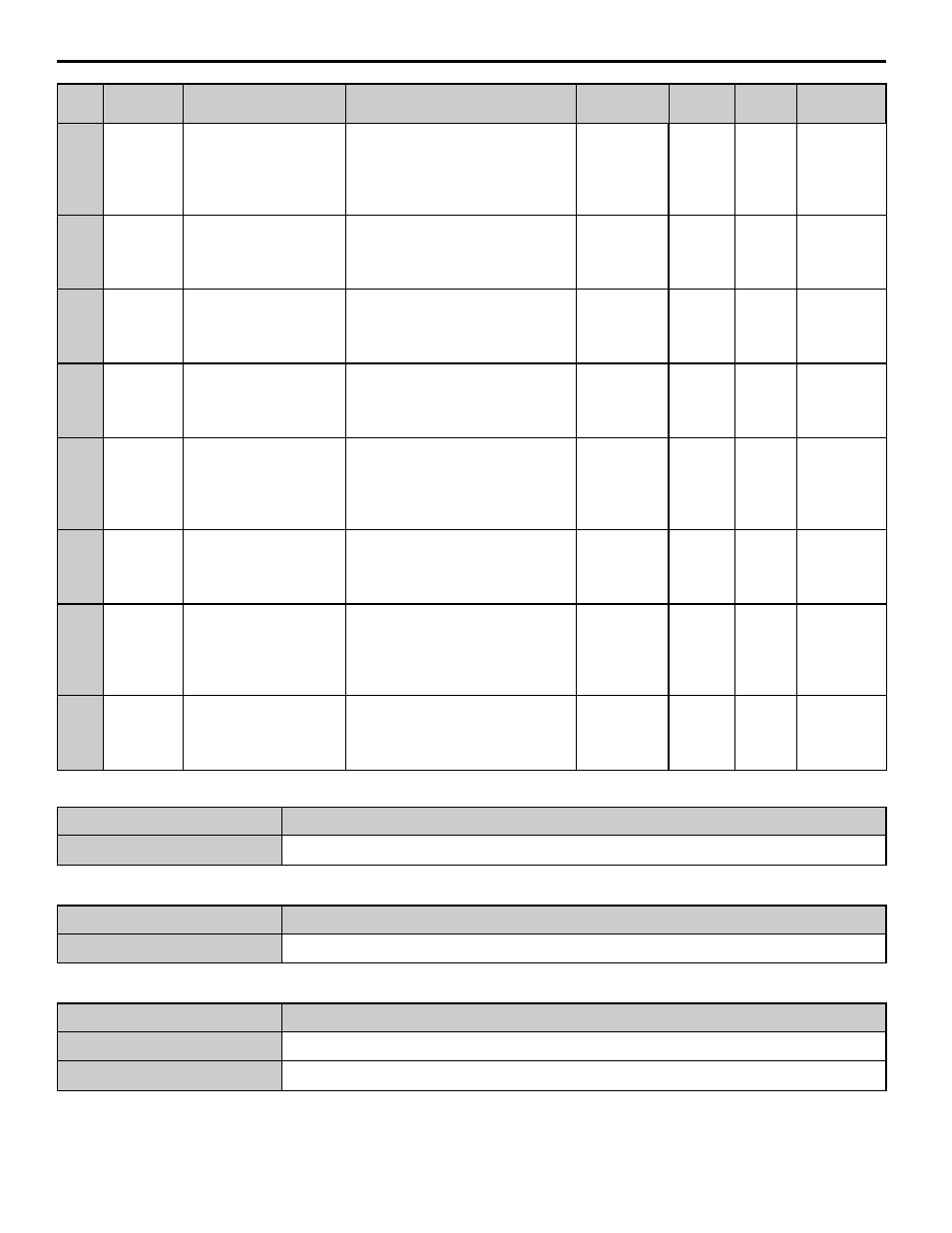
Table 5 Modified Group Text
Table 6 Additional Group Text
Table 7 Modified Function Text
P2-06
060Fh
Motor Gear Ratio 1
Motor Ratio 1
This parameter sets gear ratio 1 between the driven
motor shaft and the spindle when the drive is set for
an indirect drive configuration. A setting of 2.0000
means that there are two motor shaft revolutions for
every revolution of the spindle.
Configuration 2: Indirect Drive with Orientation
Encoder on page 23
.
0.0400 to 2.5000
1.0000
No
– – – Y– – N
P2-07
0610h
Motor Gear Ratio 2
Motor Ratio 2
This parameter sets gear ratio 2 between the driven
motor shaft and the spindle.
0.0400 to 2.5000
1.0000
No
– – – Y– – N
P2-08
0611h
Motor Gear Ratio 3
Motor Ratio 3
This parameter sets gear ratio 3 between the driven
motor shaft and the spindle.
0.0400 to 2.5000
1.0000
No
– – – Y– – N
P2-09
0612h
Orientation ASR Enable
ORT ASR Enable
This parameter enables the ASR Proportional Gain
override used during orientation.
0: Disabled
1: Enabled
0 to 1
0
No
– – – Y– – N
P2-10
0613h
ASR P Gain 3
ASR P Gain 3
This parameter sets the ASR Proportional Gain used
for orientation and becomes active whenever an
Orient Digital Input (H1-0
= 80 ~ 82) is present.
This parameter overrides C5-01 and C5-03 when
P2-09 = 1. The active proportional gain
(C5-01 or C5-03) is ramped to the P2-10 value
using the P2-11 time setting.
0.00 to 300.00
20.00
Yes
– – – Y– – N
P2-11
0623h
ASR I Time 3
ASR I Time 3
This parameter sets the ASR Integral Time used for
orientation and becomes active whenever an Orient
Digital Input (H1-0
= 80 ~ 82) is present.
This parameter automatically overrides C5-02 and
C5-04.
0.000 to
10.000 sec
0.500
Yes
– – – Y– – N
P2-12
0624h
ASR P Gain 4
ASR P Gain 4
This parameter sets the ASR Proportional Gain used
for orientation and becomes active whenever the
Orientation Compete Digital Output (H2-0
= 40)
is active. This parameter overrides C5-01, C5-03,
and P2-10 ASR gain settings when P2-09 = 1. The
active P2-10 proportional gain is ramped to the P2-
12 value using the P2-13 time setting.
0.00 to 300.00
20.00
Yes
– – – Y– – N
P2-13
0625h
ASR I Time 4
ASR I Time 4
This parameter sets the ASR Integral Time used for
orientation and becomes active whenever the
Orientation Compete Digital Output (H2-0
= 40)
is active. This parameter automatically overrides
C5-02, C5-04, and P2-11.
0.000 to
10.000 sec
0.500
Yes
– – – Y– – N
Function Group
Function Group Name
Digital Operator Display
S
High Frequency
High Frequency
Function Group
Function Group Name
Digital Operator Display
P
Spindle Orient Group
Spindle Orient
Function No.
Function Name
Digital Operator Display
S1
High Frequency Control
HighFreq Control
S2
Control Mode Switchover
Ctrl Mode Switch
No.
MEMOBUS/
Modbus
Address
Name
Digital Operator Display
Description
Range
Default
Value
Change
During
Run
Control Method/
Access Level