Orient from run: frequency reference below p1-02, Orient from stop, 2 spindle orientation – Yaskawa A1000 AC Drive Spindle Orientation User Manual
Page 20
2 Spindle Orientation
20
YASKAWA TM.A1000SW.063 Spindle Orientation A1000 Custom Software Supplement
Once the position is maintained within the Complete Detection Set window P1-05 for the length of time defined by the
ORT Set Time P1-07, the H2-0
digital output programmed to Orient Complete (40h) is set and Zero Servo control is
enabled. With Zero Servo control enabled, any remaining position error is resolved by the Zero Servo algorithm.
Also, if Orientation ASR Enable parameter P2-09 is enabled, the P2-10 ASR Gain setting is ramped to the P2-12
(ASR P Gain 4) setting over the time specified by parameter P2-13 (ASR I Time 4).
Zero Servo Gain parameter b9-01 controls the responsiveness of the drive when external loads are applied. If an external
influence forces the position of the spindle outside of the P1-06 Orientation Detection Complete Reset Window, the
Orient Complete digital output is reset but the drive remains in Zero Servo Control. A detailed description of Orientation
Complete Detection Set and Reset windows can be found in
Orientation Set/Reset Window on page 28
Note: The position control algorithm requires control of the drive at frequencies well below 1 Hz. Therefore, drive parameters b1-05
and E1-09 should remain programmed to their default values.
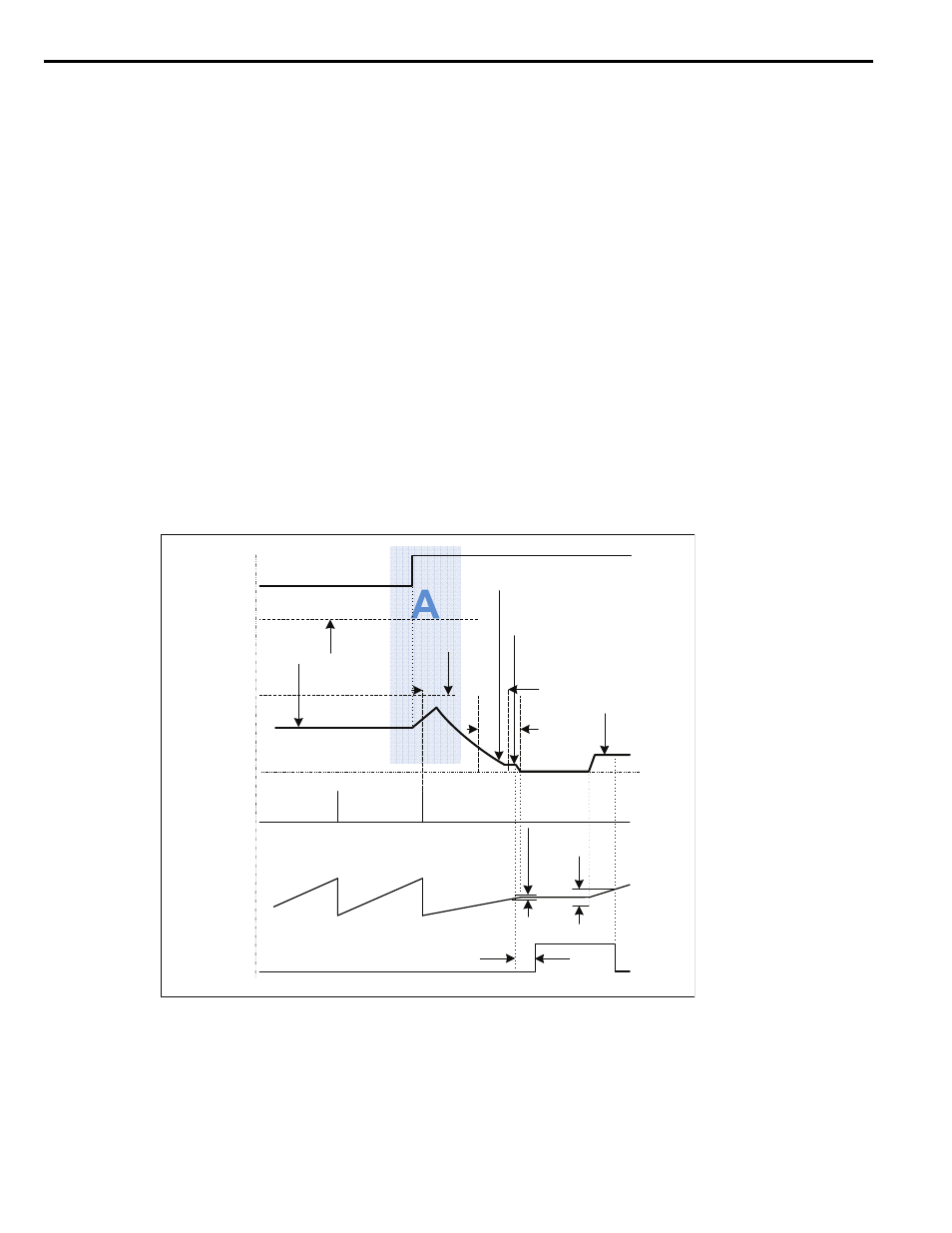
Orient from Run: Frequency Reference below P1-02
If the drive is running at a frequency reference below P1-02 and an orient digital input is closed, the drive accelerates
towards the P1-02 Creep Speed using the drive Acceleration Time C1-0
until it finds the marker pulse. The drive ramps
its current ASR P Gain to ASR P Gain 3 (P2-10) if Orientation ASR Enable parameter P2-09 is enabled. Once the marker
pulse is found, s-curves are disabled and the position-error is calculated in the same fashion as the Orient from Run
example discussed in the above section.
Note: If the drive has an active run command and a frequency reference of 0 Hz, the drive accelerates in the commanded run direction
when an 80h Orient CMD is given. If an 81h Orient CMD FWD or 82h Orient CMD REV is given, the drive ignores the
commanded run direction.
Figure 5
Figure 5 Orientation Profile from Below P1-02
Orient from Stop
An orient from stop is performed when the spindle is at rest, no RUN command is present, and one of the 81h Orient
CMD FWD or 82h Orient CMD REV digital inputs is closed. Separate run commands are not required to perform an
orient from stop, as the 81h and 82h digital inputs provide their own run command to the drive.
ORT Set Time (P1-07)
Orient Complete
A/B Pulse Count
(Equivalent to
Shaft Angle)
Z Marker Pulse
Machine Speed
(Hz)
Accel Time
(C1-0X)
Orient Speed
(P1-01)
Creep Speed
(P1-02)
Rotation due to
External Influence
ORT Set Window
(P1-05)
ORT Rst Window
(P1-06)
(H2-0X = 40h)
Orient Comp Dist
(P1-09)
Creep Distance
(P1-03)
Approach Speed
(P1-04)
Frequency Reference
(determined by b1-01)
Position-Error × P1-08 Gain
Based Speed
Orient Digital Input
(H1-0X = 80/81/82h)