Drive monitors, 2 spindle orientation – Yaskawa A1000 AC Drive Spindle Orientation User Manual
Page 26
2 Spindle Orientation
26
YASKAWA TM.A1000SW.063 Spindle Orientation A1000 Custom Software Supplement
• Sequential Reset (83h)
When closed, this parameter sets the active orientation offset to the value specified in Marker Offset 1 parameter P2-02.
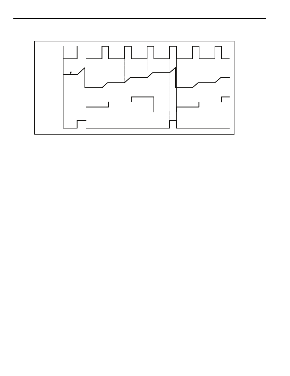
Figure 10
Figure 10 Operation of Sequential Orientation Feature
P2-01 = 2, Memobus COM Selection
This method uses the network communication offset (Memobus Register 0012h) as the offset from the marker pulse.
When this setting is selected, parameters P2-02, P2-03, P2-04, and P2-05 are ignored. If the drive power is cycled, this
register is reset to 0 counts.
An orient offset written to this register is displayed in monitor U7-06. If a write is performed to the Memobus register
while an orient digital input is active, the value (and the U7-06 monitor) is not effective until the Orient Digital Input
(80h, 81h, or 82h) is released.
Drive Monitors
This software has five monitors to aid in the setup and operation of the spindle orient system.
U7-02: Distance From Marker
This monitor displays the number of counts the orientation encoder is past the marker pulse (relative to the direction of
travel). The monitor counts from 0 up to the number of (F1-01 x 4) encoder counts if CN5-C is the orientation encoder
card, or the number of (F1-31 x 4) encoder counts if the orientation encoder card is CN5-B. Offsets which are specified as
greater than one revolution are normalized to the encoder PPR.
When power to the drive is reset, this monitor is reset to 0. Since the orientation of the spindle is unknown while the drive
is without power, upon power up the monitor alternates “Dist from Marker” / “Looking for C/Z” until the drive finds the
first marker pulse. Once the marker pulse is found, the monitor resets to 0 once again, and the “Looking for C/Z” message
clears.
When the drive exceeds the S2-01 Control Mode Switch Frequency (S2-11 if Motor 2 is selected), the encoder PPR may
exceed the input frequency limit of the PG-X3/PG-B3 Encoder (PG) Feedback Card. Therefore, this monitor ceases to
update when the frequency reference is above S2-01. The monitor alternates the text “Dist from Marker” / “PG Freq
Limit” until the drive frequency is less than S2-01 and the marker pulse is located.
U7-03: Distance from Offset
This monitor displays the number of counts the orientation encoder is past the current offset (relative to forward rotation).
The current offset value is latched at the rising edge of an orient digital input (as displayed in monitor U7-04). The
monitor counts from 0 up to the number of (F1-01 x 4) encoder counts if CN5-C is the orientation encoder card, or the
number of (F1-31 x 4) encoder counts if the orientation encoder card is CN5-B. Offsets which are specified as greater
than one revolution are normalized to the encoder PPR.
Orient CMD FWD
(H1-0X = 81h)
Distance From
Marker
(U7-02)
P2-02
P2-03
P2-04
P2-05
P2-02
P2-03
P2-04
Home Position
(H2-0X = 41h)
Sequential Step
Offset
P2-03
P2-04
P2-05
P2-02
P2-03
P2-04
P2-05
P2-02
Starting
Offset