Function description, Refer to, 2 spindle orientation – Yaskawa A1000 AC Drive Spindle Orientation User Manual
Page 17
2 Spindle Orientation
YASKAWA TM.A1000SW.063 Spindle Orientation A1000 Custom Software Supplement
17
Function Description
The spindle orientation function begins when one of the orient digital inputs (80h, 81h, or 82h) outlined in
closed. These orient digital inputs can be broken into two modes: Orient from Run, and Orient from Stop. These two
modes are discussed later in this section.
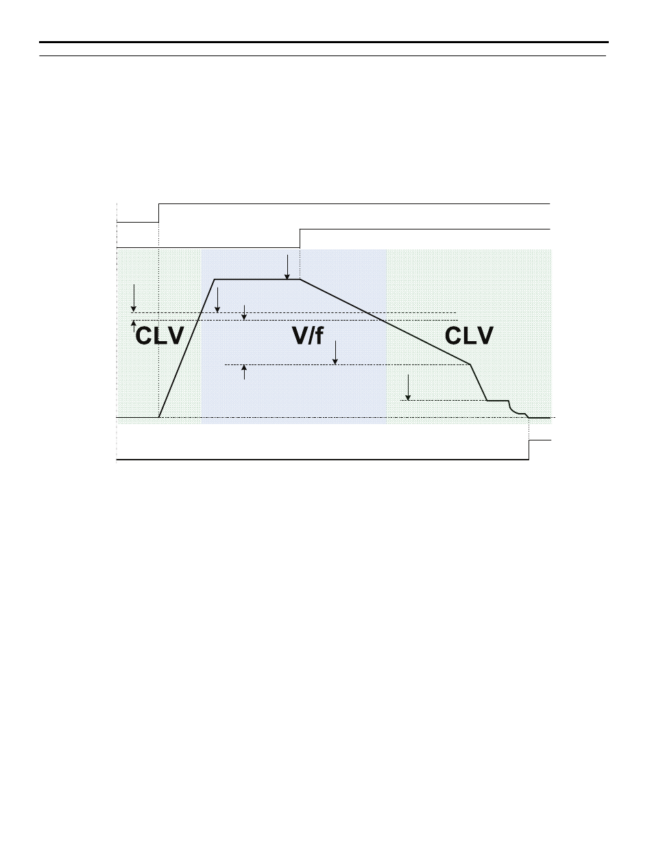
Orient only occurs when the drive is in Closed Loop Vector (CLV) control mode. This can be achieved by setting the P1-
02 Creep Speed below the window established by the S2-01 Control Mode Switchover Frequency and the S2-02 Control
mode Switchover Bandwidth.
shows how the drive returns to Closed Loop Vector operation once an orient is
commanded.
Figure 2
Figure 2 Orient Operation with High Frequency Switchover
Machine Speed
(Hz)
Run Command
Decel Time
(C1-0X)
Orient Speed
(P1-01)
Creep Speed
(P1-02)
ORT Dec Time
(P1-12)
Frequency Reference
(determined by b1-01)
Orient Digital Input
(H1-0X = 80/81/82h)
Accel Time
(C1-0X)
Control Mode Switchover
Frequency (S2-01)
Control Mode Switchover
Bandwidth (S2-02)
Orient Complete
(H2-0X = 40h)
Frequency [(S2-01) ‒ (S2-02)]
must be greater than P1-01 or
OPE12 error will occur.