Drive wiring examples, 2 spindle orientation – Yaskawa A1000 AC Drive Spindle Orientation User Manual
Page 30
2 Spindle Orientation
30
YASKAWA TM.A1000SW.063 Spindle Orientation A1000 Custom Software Supplement
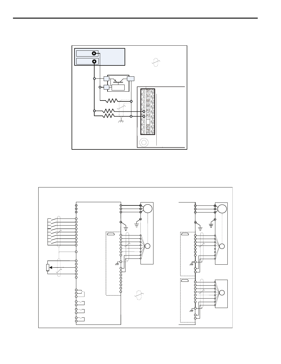
is an example of how a +12 Vdc current sourcing (open collector PNP) switch can be used to trigger the
marker pulse input.
Figure 14
Figure 14 External Marker Pulse Wiring Diagram: PNP
Drive Wiring Examples
The examples in
are typical wiring diagrams for the direct and indirect positioning methods discussed in
Application Configurations on page 23
.
Figure 15
Figure 15 Wiring of Drive for Application Examples
PG-X3 Encoder
Feedback Card
12VDC +/- 5%
Power Supply
+12VDC
Common
R3
R1
R2
PNP External Marker
All resistors 560 Ω,
tolerance 10%, ½ Watt
Shielded
Twisted Pair
OC
-
+
IM
GND
PG-X3
Op
tion
Card
PG
U/T1
V/T2
W/T3
A1000
R/L1
S/L2
T/L3
S1
S2
S3
S4
S5
S6
S7
S8
E (G)
A1 Input (0 to +/- 10VDC)
A2 Input
+V Supply (+10.5VDC)
A3 Input
AC Common
1
B
T
2
B
T
Motor
Example 1: Closed Loop Vector
Control ‒ Direct Drive
IP
IG
a+
a-
b+
b-
M3
M4
MA
MB
MC
-V Supply (-10.5VDC)
Speed Reference
H2-0X = 41h:
Home Position
H2-0X = 40h:
Orient Complete
Position
Encoder
Note: An external power supply may be
required. The PG-X3 has a 200mA
power supply. Check the rated current of
both encoders.
Example 2: Closed Loop Vector
Control with Position Encoder
M1
M2
M5
M6
Fault
z+
z-
A+
A-
B+
B-
Z+
Z-
SD
FE
PG Power
PG GND
Forward Run
Reverse Run
Orient CMD
Offset Sel 1
SN
2kΩ
Shielded Twisted
Pair
IM
GND
PG-X3
Option C
ard 1
PG
U/T1
V/T2
W/T3
TB2
T
B1
Motor
IP
IG
A+
A-
B+
B-
Z+
Z-
SD
FE
PG Power
PG GND
PG-X3 Option Ca
rd 2
PG
TB2
T
B1
IP
IG
A+
A-
B+
B-
Z+
Z-
SD
FE
PG Power
PG GND
Motor
Encoder
CN5-C
CN5-C
CN5-B
(H1-01 = 40h)
(H1-02 = 41h)
(H1-03 = 80h)
(H1-04 = 84h)