Application configurations, 2 spindle orientation, Typical applications are as follows – Yaskawa A1000 AC Drive Spindle Orientation User Manual
Page 23: Configuration 1: direct drive
2 Spindle Orientation
YASKAWA TM.A1000SW.063 Spindle Orientation A1000 Custom Software Supplement
23
Application Configurations
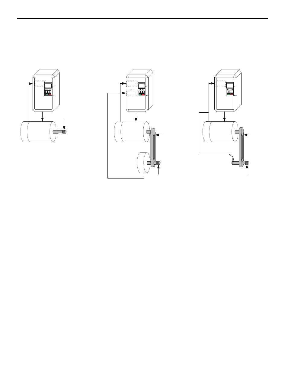
Typical applications are as follows:
Figure 8
Figure 8 Application Configurations for Applicable Control Methods
Configuration 1: Direct Drive
This is a direct drive system where the encoder, motor and spindle shafts are directly coupled. This system can use the
motor's encoder for orientation and closed loop vector control (A1-02 = 3) of the motor to provide the best performance.
The orientation encoder must have a marker pulse (referred to as the Z or C pulse).
Configuration 2: Indirect Drive with Orientation Encoder
This is an indirect drive system where the motor and the spindle shaft are connected through a drive train. The orientation
encoder is coupled to the spindle shaft which is used for spindle positioning, while the motor encoder is used for closed
loop vector control.
Both encoders must have quadrature feedback (A and B channels with compliments). The orientation encoder must also
have a marker pulse (referred to as the Z or C pulse).
Note: If the Orient encoder phasing is incorrect (A and B phases are swapped), the drive fails to orient. The symptom of incorrect
orientation encoder phasing would be a drive that ramps down to the P1-02 creep speed but does not orient. If the orientation
encoder is CN5-B, then changing PG 2 Rotation Selection Parameter F1-32 or swapping A/B encoder wires on the CN5-B option
card should resolve the issue.
In this configuration, the gear ratio of the drive train must be expressed as an exact number of motor revolutions per
revolution of the spindle. By default, the software is programmed with a gear ratio of 1.0000. If the motor and the
proximity sensor are connected by a gear train, their ratio can be expressed within the range of 0.0400 to 2.5000. A ratio
of 2.0000 means that there are two motor shaft revolutions for every revolution of the spindle (and every proximity sensor
pulse). This gear ratio may be changed by modifying parameters P2-06, P2-07, and P2-08, and then selecting the gear
ratio using Gear Ratio Select digital inputs 86h and 87h. If neither of the digital inputs 86h or 87h is programmed, P2-06
is the active gear ratio.
Mo
to
r
En
co
de
r
Machine
Motor
Configuration 2: Indirect Drive with
Orientation Encoder
Configuration 1: Direct Drive
PG-X3
PG-X3
PG-X3
Orientated
Machine Part
O
ri
e
nt
ation
En
co
de
r
Orientated
Machine Part
Drivetrain
(Gear Ratio)
CN5-B
CN5
-C
CN5
-C
Mo
to
r
Enc
o
d
e
r
Ch A/B/Z
Ch A/B/Z
Ch A/B
Machine
Motor
Mo
tor
En
co
de
r
Machine
Motor
Configuration 3: Indirect Drive with
Proximity Sensor
PG-X3
Proximity
Sensor
Orientated
Machine Part
Drivetrain
(Gear Ratio)
CN
5-
C
Ch Z
Ch A/B