Orientation, Orientation set/reset window, 2 spindle orientation – Yaskawa A1000 AC Drive Spindle Orientation User Manual
Page 28: Figure 11 asr gain/time change during orient, Figure 12 orientation set and reset windows
2 Spindle Orientation
28
YASKAWA TM.A1000SW.063 Spindle Orientation A1000 Custom Software Supplement
Figure 11
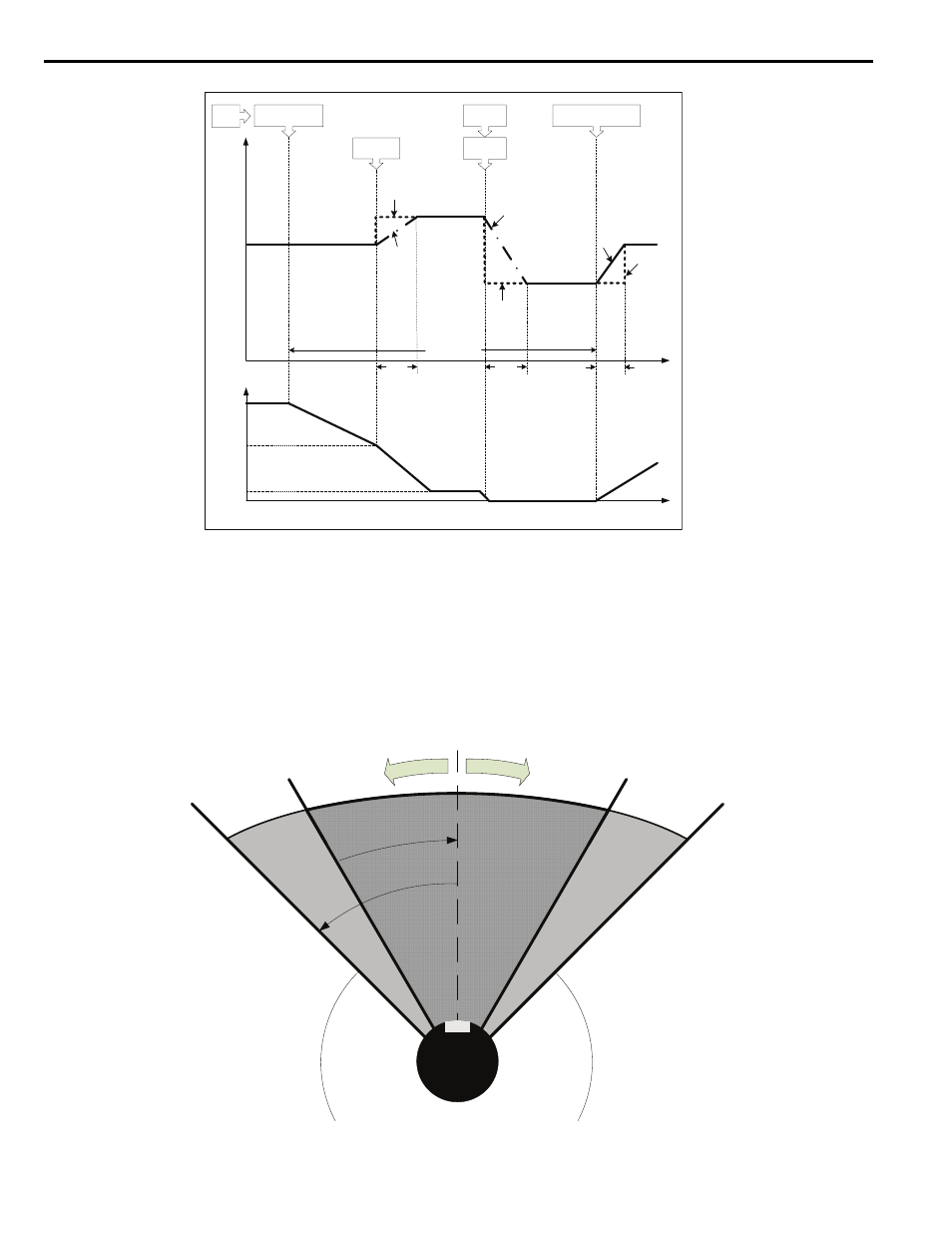
Figure 11 ASR Gain/Time Change During Orient
Orientation Set/Reset Window
visualizes the Orientation windows P1-05 and P1-06. The motor enters the dark grey Orient Set Window once
the difference between the current position and the desired Marker Offset is less than P1-05 counts. If the current position
is maintained within the dark grey window for longer than the Orientation Set Time P1-07, the multi-function digital
output H2-
set to 40h will go high. This output remains high as long as the shaft maintains its position within
+/- P1-06 counts of the Marker Offset, which is the light grey Orientation Reset Window in
.
Figure 12
Figure 12 Orientation Set and Reset Windows
*P = C5-01
*I = C5-02
0
ASR
P Gain,
I Time
P = P2-10
I = P2-11
Time [s]
P2-11
P
I
During Orient
P2-13
P
I
P = P2-12
I = P2-13
Orient
Complete
Acceleration,
Orient CMD Removed
Deceleration,
80h Orient CMD
Event
*Assumes C5-07 = 0.0Hz, speed-dependent ASR values disabled.
Freq Ref =
P1-01
Zero
Servo
P
Motor
Speed
[Hz]
(U1-05)
Time [s]
0
P1-01
P1-02
I
C5-02
Motor Shaft
Orient Position
Orient Set
Window
Orient
Reset
Window
S et i
f < P
1-05
coun
ts
R ese
t if >
P1-0
6 cou
nts