Refer to orient position offset selection, Refer to orient position offset selection on, Orient position offset – Yaskawa A1000 AC Drive Spindle Orientation User Manual
Page 25: The d, 1 and, For more, Refer
2 Spindle Orientation
YASKAWA TM.A1000SW.063 Spindle Orientation A1000 Custom Software Supplement
25
Proximity Sensor Pulse Width parameter P1-14 applies an offset to the proximity sensor pulse when the spindle is
commanded to orient in the reverse direction. With parameter P1-14 set to 0 counts and a Marker Offset P2-02 = 0, the
proximity sensor orients to opposite sides of the target when orienting from the forward and reverse directions. When P1-
14 is set to the width of the target in encoder counts, the pulse width is applied in a way such that the spindle always
orients to the side of the target which provides a rising edge when the spindle is turned in the forward direction.
Proximity sensor pulse width can be measured in counts by slowly turning the spindle and observing the elapsed counts
on the U7-02 (Distance from Marker) monitor between the rising and falling edges of the sensor over the target. Some
proximity sensors have an LED indicator to indicate the presence or absence of a target. If this is not present; the output of
the proximity sensor can be viewed on an oscilloscope or measured using a multimeter. On applications requiring higher
precision of orientation, the elapsed counts can be measured by simultaneously monitoring the A/B/Z channels of the
encoder and proximity sensor and observing the elapsed counts during the period in which the marker pulse is sensed.
Orient Position Offset Selection
By default, the software is programmed with an offset of 0 counts from the marker pulse. This means that the spindle
aligns itself to the marker pulse every time an orient is commanded. The drive may be oriented to another position by
setting Marker Offset Selection parameter P2-01 to one of three selections outlined below.
The desired offsets must be programmed into marker offset parameters P2-02 through P2-05 or set using the Memobus
register 0012h. Offsets which are specified as greater than one revolution are normalized to the encoder PPR x 4. If the
offset values are not known, they can be found by rotating the spindle by hand. To find an offset value after powering up
the drive, rotate the motor shaft until the orientation encoder axis turns for 1 rotation (360 deg), or until the drive
recognizes the marker pulse. The drive indicates that the marker pulse is found once monitors U7-02 (Distance from
Marker) and U7-03 (Distance from Offset) stop flashing “Looking for C/Z”. Rotate the machine to the desired position by
hand or by the using the run inputs. Read the marker offset value of U7-02 and enter the value in one of the parameters
P2-02 through P2-05 or the Memobus register.
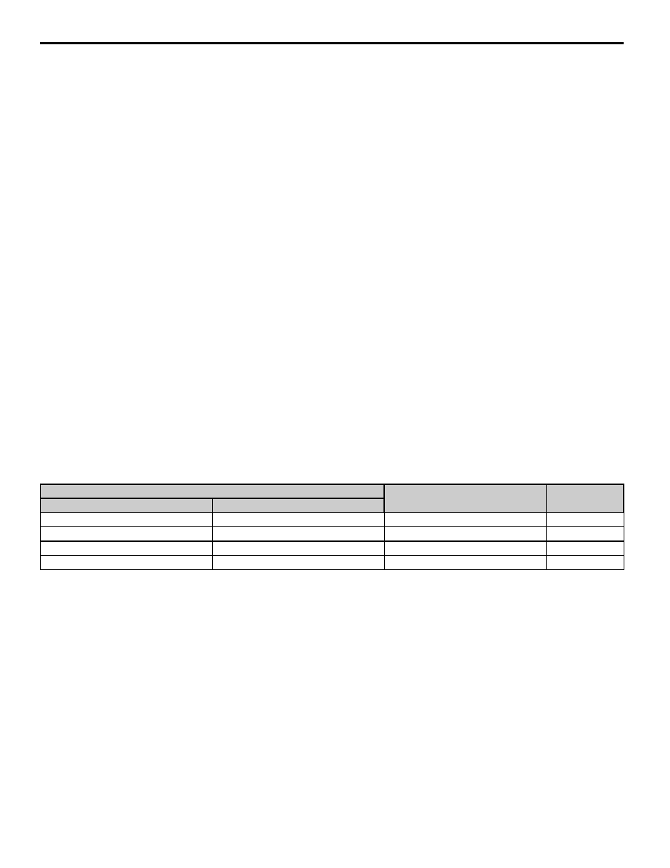
P2-01 = 0, Digital Input Selection
This method uses the Offset Selection digital inputs 84h and 85h to determine the orient offset based on parameters
P2-02, P2-03, P2-04, and P2-05. When no digital input is programmed or selected, P2-02 is used as the offset.
Note: Offset Selection digital inputs 84h and 85h are only effective while Marker Offset Selection parameter P2-01 = 0.
P2-01 = 1, Sequential Selection
This method rotates through the offset values specified in parameters P2-02, P2-03, P2-04, and P2-05 each time an orient
is commanded. If the drive power is reset, the offset is re-initialized to P2-02.
demonstrates operation of the sequential offset mode and the Home Position digital output 41h. The Home
Position digital output is functional only when parameter P2-01 is programmed to sequential selection. When the drive
powers up and the first orient digital input is closed, the drive sets the 41h Home Position digital output and orient to the
P2-02 offset. When the orient digital input is removed, the Home Position digital output is opened. The drive orients to
the P2-03, P2-04 and P2-05 offsets when subsequent orient are commanded. When the orient digital input is removed
after the P2-05 offset, the offset returns to P2-02.
When an orient digital input is activated, the drive chooses the orient offset position. This position remains in effect until
all orient digital inputs are removed. If the state of the orient position offset digital inputs changes during orientation, the
selection is not active until the orient digital inputs are removed. One additional digital input is available only during
sequential selection:
Multi-Function Digital Input (H1- ) Selection
Effective Parameter
U7-05
Seq Step
85: Offset Selection 2
84: Offset Selection 1
Open
Open
P2-02: Marker Offset 1
0
Open
Closed
P2-03: Marker Offset 2
1
Closed
Open
P2-04: Marker Offset 3
2
Closed
Closed
P2-05: Marker Offset 4
3