Dip switch programmable functions summary, Auto transfer to bypass, Power up mode – Yaskawa E7B Drive Bypass System User Manual
Page 13
Yaskawa Electric America, Inc.
Installation Guide IG.E7B.02 Rev: 04-11
Date: 11-1-04 Page 11 of 46
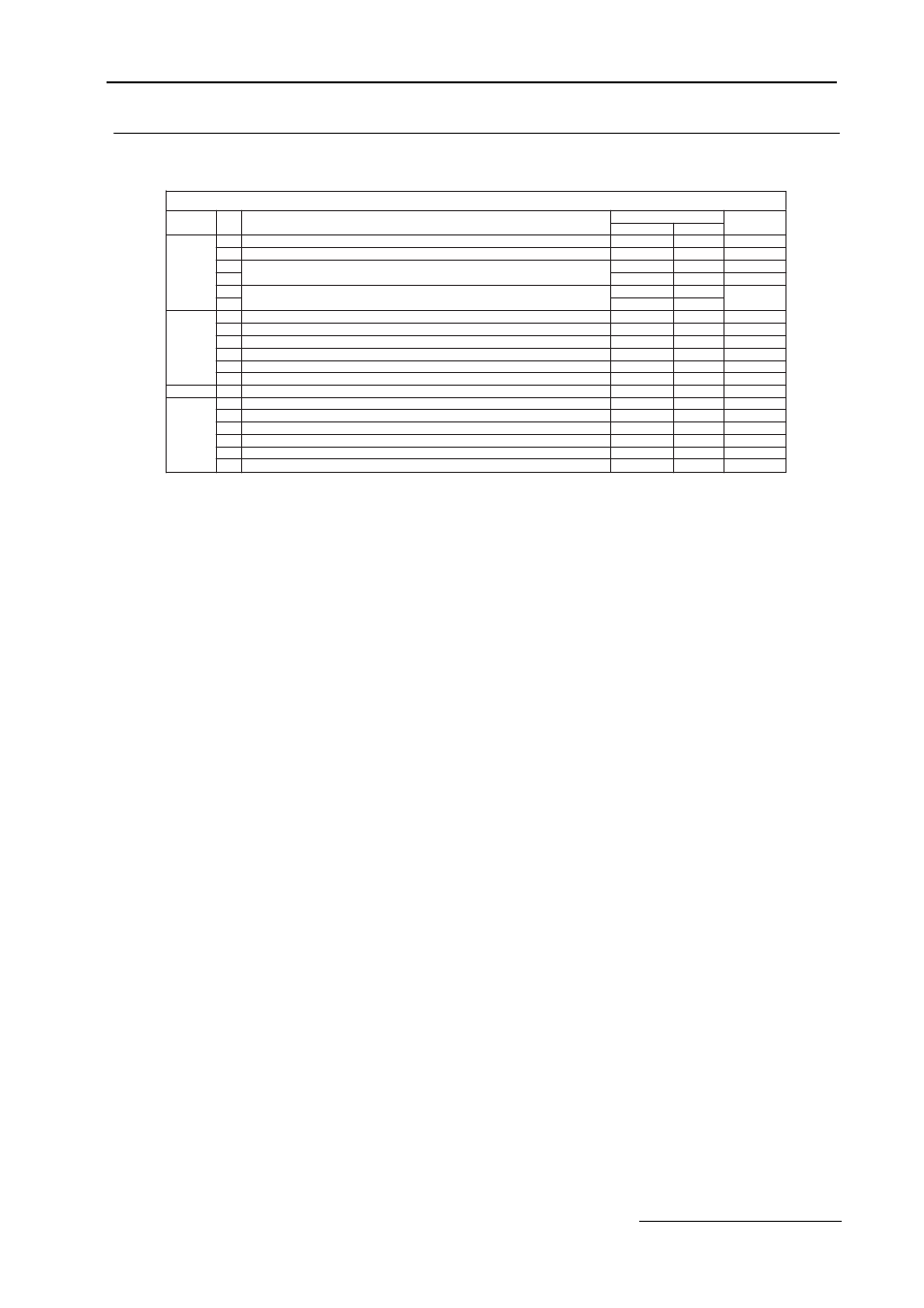
DIP Switch Programmable Functions Summary
Auto Transfer to Bypass
When enabled (DIP switch S2-1 ON), the Bypass unit will automatically switch into Bypass mode on a Drive fault.
After clearing the Drive fault condition, the function resets by moving the disconnect switch to the OFF position and
waiting for the keypad to go blank. CAUTION: Before selecting this function in fan applications, care must be taken
to ensure that the ductwork is designed to handle the pressure resulting from full speed operation with the VAV termi-
nal unit dampers at minimum position or closed. The factory default for this function is disabled.
Power Up Mode
The Drive/Bypass electronic interface can be configured (via a DIP switch) to be in the AUTO mode or OFF when
power is applied to the unit. This function is controlled by DIP switch S2-2, ON for AUTO operation on power up.
The factory default is to power up to the OFF mode.
1
2
3
4
3
4
1
2
3
4
5
6
7
4-6
1-6
8
S1
ON
OFF
IN
OUT
FACTORY
SETTING
4-20MADC
0-10VDC
ON
ON
OFF
YES
YES
YES
YES
YES
NO
INACTIVE
ACTIVE
INACTIVE
ACTIVE
DIP
SWITCH
SETTINGS
DESCRIPTION
S2
S3
S4
POS.
SAFETY INTERLOCKS AT TB1(1)
BAS/DAMPER INTERLOCKS AT TB1(3)
TB3(3) CONNECTED TO DRIVE ANALOG INPUT 2 (A2)
TB3(3) CONNECTED TO DRIVE ANALOG INPUT 1 (A1)
DRIVE ANALOG INPUT 2 (A2) SIGNAL (H3-08="0", FOR 0-10VDC)
1
2
AUTO TRANSFER TO BYPASS UPON A DRIVE FAULT
OFF
AUTO
OFF
OFF
ACTIVE
ACTIVE
ACTIVE
ACTIVE
ACTIVE
ACTIVE
ACTIVE
INACTIVE
OFF
OFF
OFF
OFF
OFF
OFF
OFF
OFF
INACTIVE
INACTIVE
INACTIVE
INACTIVE
INACTIVE
INACTIVE
POWER UP IN THE "OFF" OR "AUTO" MODE
3
POWER UP IN THE MAINTENANCE MODE
SEE TABLE 2.6
SEE TABLE 2.6
RESERVED FOR FUTURE EXPANSION MUST BE AT FACTORY SETTING
SPEED COMMAND FROM DRIVE TERMINAL A2, WITH SERIAL COMM.
RESERVED FOR FUTURE EXPANSION MUST BE AT FACTORY SETTING
RESERVED FOR FUTURE EXPANSION MUST BE AT FACTORY SETTING
RESERVED FOR FUTURE EXPANSION MUST BE AT FACTORY SETTING
RESERVED FOR FUTURE EXPANSION MUST BE AT FACTORY SETTING
SERIAL COMMUNICATIONS TERMINATING RESISTANCE
SEE TABLE 5.2
SEE TABLE 5.2
TABLE 1.10 DIP Switch Functions