Yaskawa E7B Drive Bypass System User Manual
Page 8
Yaskawa Electric America, Inc.
Installation Guide IG.E7B.02 Rev: 04-11
Date: 11-1-04 Page 6 of 46
Analog Input (Drive Speed Control Circuit) Wiring
Keep this lead length as short as possible (50 m max.) to maintain signal quality. Insulated twisted shielded pair wire
(2 conductor # 18 ga, Belden 8760 or equivalent) is required. Do not run these wires in the same conduits as other AC
power or control wires. The shield must be connected on this end only, stub and isolate the other end. The signal
employed is 4 to 20 mA with parameter H3-08 set for “2: 4 - 20 mA”. For 0 to 10 VDC, parameter H3-08 is set for
“0: 0 - 10 VDC” and the control PCB DIP switch S1-2 must be in the OFF position.
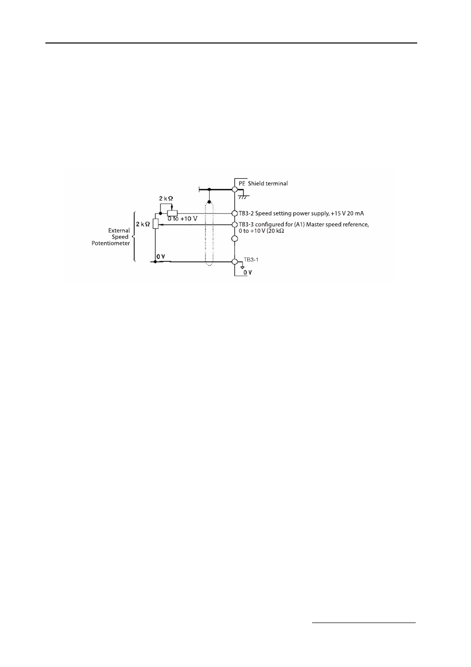
When setting speed commands from an external speed potentiometer (and not from a Digital Operator), use shielded
twisted-pair wires and ground the shield to terminal PE, as shown in Figure 1.3. Terminal numbers and wire sizes are
shown in Table 1.11.
Fig 1.3 Analog Input Terminal Configuration