Table 1.14 drive operational status indicators, Drive digital operator/keypad – Yaskawa E7B Drive Bypass System User Manual
Page 22
Yaskawa Electric America, Inc.
Installation Guide IG.E7B.02 Rev: 04-11
Date: 11-1-04 Page 20 of 46
Drive Digital Operator/Keypad
Drive Operational Status Indicators
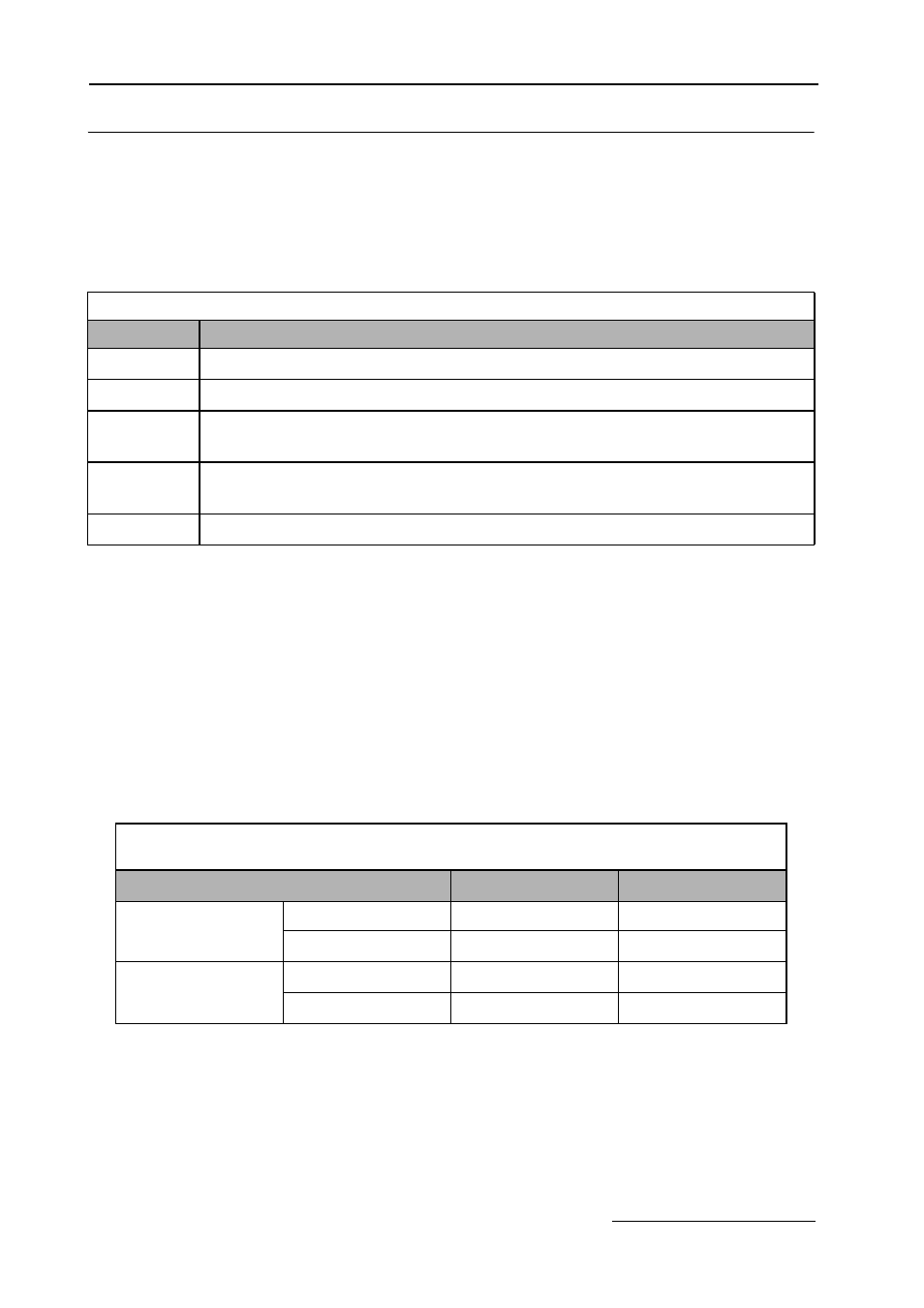
The definition of the Drive operational status indicators are shown in Table 1.14.
Drive REMOTE Sequence (SEQ) and REMOTE Reference (REF) indicators
The Bypass operates differently than a stand alone Drive with regard to these two indicators. The Bypass control logic
interfaces with the Drive via terminals that would be used, in a Drive only installation, for the REMOTE Sequence (Run
Command), and REMOTE Reference (Speed Command).
Since these terminals are active and the appropriate parameters configured for the Bypass unit operation, the
REMOTE Sequence and REMOTE Reference LED’s will be lit even when the H/O/A HAND button is pressed (local
control), providing both the run and speed command from the local control panel. The control signals are “Local” to
the Drive and Bypass unit, but “Remote” from the Drive itself.
An exception to this rule occurs for the REMOTE REF indicator when serial communication is employed. See Table
1.15.
Table 1.14 Drive Operational Status Indicators
Indicator
Definition
FWD
Lit (red) when a forward run command is input. Also lit when the Drive is in “Hand” Mode.
REV
Lit (red) when a reverse run command is input.
REMOTE
SEQ
Lit (red) when set up for remote run command, see Table 1.15.
REMOTE
REF
Lit (red) when set up for remote speed command, see Table 1.15.
ALARM
Lit (red) when a fault has occurred and flashing when an alarm has occurred.
Table 1.15 Drive REMOTE Sequence (SEQ) and
REMOTE Reference (REF) Indicators
Indicator
HAND
AUTO
Analog Input
REMOTE SEQ
ON
ON
REMOTE REF
ON
ON
Serial COM Input
REMOTE SEQ
OFF
ON
REMOTE REF
OFF
ON