Table 1.6 analog outputs, Table 1.7 analog output proportional variables, Analog outputs – Yaskawa E7B Drive Bypass System User Manual
Page 9
Yaskawa Electric America, Inc.
Installation Guide IG.E7B.02 Rev: 04-11
Date: 11-1-04 Page 7 of 46
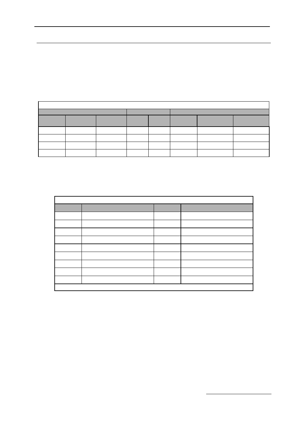
Analog Outputs
Two analog outputs are provided, both can be configured for a signal level of 0 to 10 VDC or 4 to 20 mA. The signal
level is controlled by the position of jumpers J2 and J3 on Control PCB A2 and by the values selected for Drive
parameters H4-07 and H4-08.
Configuring the Analog Outputs:
Programming the Analog Outputs:
The TB3-4 and TB5-6 analog outputs can be programmed to be proportional to any of the following Drive variables.
See the H4-0X parameters in programming manual TM.E7.02 for additional programming details.
Table 1.6 Analog Outputs
Terminals
Jumper Position
Drive
Analog
Output
AC
Common
Signal Level
J2
J3
Terminal *
Parameter
H4-07
Parameter
H4-08
TB3-4
TB3-1
4-20 mA
1-2
N/A
FM
2: 4-20 mA
N/A
TB3-4
TB3-1
0-10 VDC
2-3
N/A
FM
0: 0-10 V
N/A
TB5-6
TB5-7
4-20 mA
N/A
1-2
AM
N/A
2: 4-20 mA
TB5-6
TB5-7
0-10 VDC
N/A
2-3
AM
N/A
0: 0-10 V
* = For Drive programming reference
Table 1.7 Analog Output Proportional Variables
Setting
Description
Setting
Description
1
Frequency Ref
20
SFS Output*
2
Output Freq
24
PI Feedback
3
Output Current
31
Not Used
6
Output Voltage
36
PI Input
7
DC Bus Voltage
37
PI Output
8
Output kWatts
38
PI Setpoint
15
Term A1 Level
51
Auto Mode Fref
16
Term A2 Level
52
Hand Mode Fref
18
Mot SEC Current
53
PI Feedback 2
* SFS is the internal soft starter signal. This signal is generated from the reference and often it passes through the accel/ decel functions.