Wiring checks, Control circuit wiring precautions – Yaskawa E7B Drive Bypass System User Manual
Page 15
Yaskawa Electric America, Inc.
Installation Guide IG.E7B.02 Rev: 04-11
Date: 11-1-04 Page 13 of 46
Wiring Checks
After all wiring is completed, perform the following checks:
1.
Is all wiring correct?
2.
Have all wire clippings, screws or other foreign material been removed from the Drive and Bypass enclosure?
3.
Are all terminal screws tight?
Control Circuit Wiring Precautions
Observe the following precautions when wiring control circuits:
1.
Separate control wiring from power/motor wiring and other high-power lines.
2.
Separate wiring for control circuit terminals for digital outputs from wiring to other control circuit terminals.
3.
If using an optional external power supply, it should be a UL Listed Class 2 power supply source.
4.
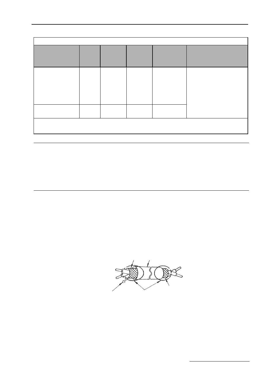
Use twisted-pair or shielded twisted-pair cables for control circuits to prevent operating faults. Prepare cable
ends as shown in Figure 1.7.
5.
Connect the shield wire to terminal PE.
6.
Insulate the shield with tape to prevent contact with other signal lines and equipment.
Fig 1.7 Preparing the Termination of Shielded Twisted-Pair Cables
Table 1.11 Terminal Numbers and Wire Sizes (Same for all Bypass Units)
Terminals
Terminal
Screws
Tightening
Torque
lb.-in.
(N•m)
Possible
Wire Sizes
AWG
(mm
2
)
Recommended
Wire Size
AWG
(mm
2
)
Wire Type
TB1-1 to 14
TB2-1 to 6
TB3-1 to 4
TB4-1 to 4
TB5-1 to 9
Phoenix
type *
3
4.2 to 5.3
(0.5 to 0.6)
Stranded
wire:
26 to 16
(0.14 to 1.5)
18
(0.75)
• Shielded, twisted-pair wire
*1
• Shielded, polyethylene-covered,
vinyl sheath cable
PE
M3.5
7.0 to 8.8
(0.8 to 1.0)
20 to 14
(0.5 to 2
*2
)
12
(1.25)
*1.Use shielded twisted-pair cables to input an external speed command.
*2.We recommend using straight solderless terminals on digital inputs to simplify wiring and improve reliability.
*3.We recommend using a thin-slot screwdriver with a 3.5 mm blade width.
Shield sheath
Insulation
Connect to shield sheath
terminal PE on PCB A2
Insulate with tape
Do not connect here.