Table 1.4 drive analog input terminals, Table 1.5 analog input - auto mode, Analog inputs – Yaskawa E7B Drive Bypass System User Manual
Page 7
Yaskawa Electric America, Inc.
Installation Guide IG.E7B.02 Rev: 04-11
Date: 11-1-04 Page 5 of 46
Analog Inputs
The Drive has two analog input terminals for use as auto mode speed command (terminals A1 & A2) and feedback
(terminal A2) input.
Control Circuit Analog Input Terminals on PCB A2
All control inputs are landed on TB1 through TB5 on PCB A2.
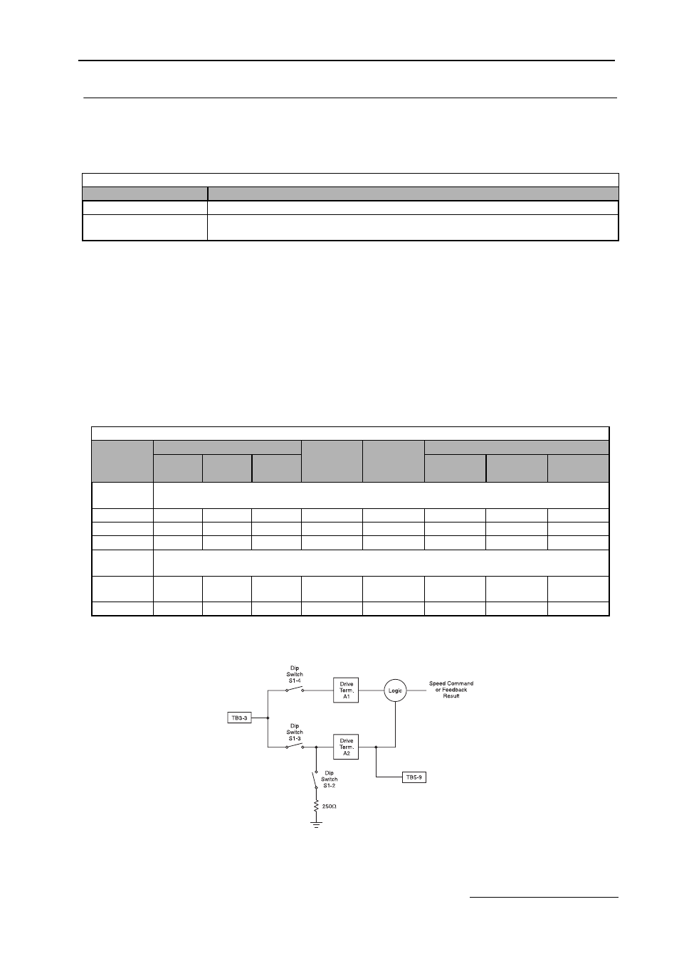
TB3-3 is an analog input terminal and may be connected to either Drive terminal A1 or Drive Terminal A2, to maxi-
mize input flexibility, using DIP switches S1-3 and S1-4. The factory default is TB3-3 connected to Drive terminal
A2. With this connection, the input signal level can be either 0 to 10 VDC or 4 to 20 mA. The signal level selection is
controlled by DIP switch S1-2 and Drive parameter H3-08.
TB5-9 is also an analog input terminal, it is always connected to Drive terminal A2.
See Table 1.5, Figure 1.2 and Schematic Diagram E7B-10 for clarification of the analog input configuration and
applications.
Analog Input PCB A2 Configuration
Fig 1.2 Analog Input PCB A2 Configuration
Table 1.4 Drive Analog Input Terminals
Terminal
Signal Level
A1
0 to 10 VDC
A2
4 to 20 mA or 1 to 10 VDC
(programmable via parameter H3-08 and DIP switch S1-2)
Table 1.5 Analog Input - Auto Mode
DIP Switches
Drive
Drive
Applications
S1-2
S1-3
S1-4
Param.
Terminal
Speed
Feedback
Diff.
H3-08
Connected
Command
Feedback
TB3-3
Signal Level
0 to 10 VDC
N/A
OFF
ON
N/A
TB3-3 to A1
X
X
X
4 to 20 mA
ON
ON
OFF
2
TB3-3 to A2
X
X
0 to 10 VDC
OFF
ON
OFF
0
TB3-3 to A2
X
X
TB5-9
Signal Level
4 to 20 mA
ON
N/A
N/A
2
TB5-9 to A2
via 3-15
Transducer
0 to 10 VDC
OFF
N/A
N/A
0
TB5-9 to A2
X