Yaskawa E7B Drive Bypass System User Manual
Page 19
Yaskawa Electric America, Inc.
Installation Guide IG.E7B.02 Rev: 04-11
Date: 11-1-04 Page 17 of 46
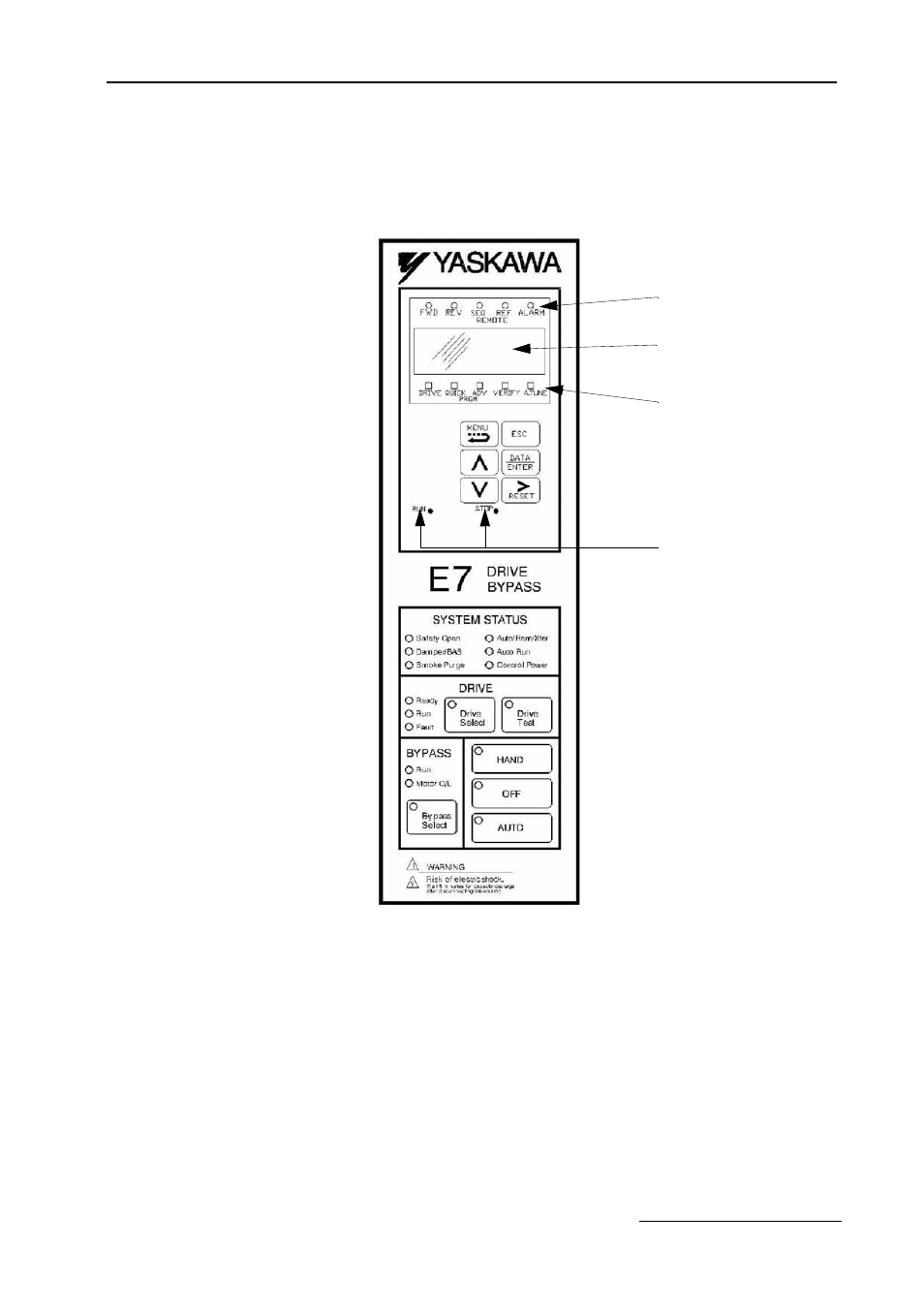
Digital Operator and Control Panel Display
The various items included on the Digital Operator Display and Control Panel are described below.
Fig 1.9A E7B_ _ _T Bypass Control Panel Component Names and Functions
The front control panel has a digital alpha/numeric display and keypad, in the upper portion, for Drive operation and
programming. The row of LEDs above the alpha/numeric display indicate Drive operational status. See Table 1.14
for an explanation. The row of LEDs below the alpha/numeric display indicate the Drive menu that is presently
active.
The lower portion of the front control panel displays the operating mode status via LEDs and controls the HAND/
OFF/AUTO functions for both the Drive and Bypass. The general rule for LED colors, in the lower portion of the
control panel, is:
Green = Normal Status
Amber = Abnormal Status
Red
= Fault Status
RUN & STOP Indicators
Drive Keypad Operator
Drive Digital
Operator/Keypad
Status Indicating LEDs
H/O/A Control Keypad
Drive/Bypass and
HAND/OFF/AUTO
Selector Keys
{
{
}
}
}
Drive Operational Status
Alpha-Numeric
Menu Indicating
LED Digital Display
LEDs