3 re-engineered servopacks for cacr-sr – Yaskawa CACR-SRxxBF User Manual
Page 34
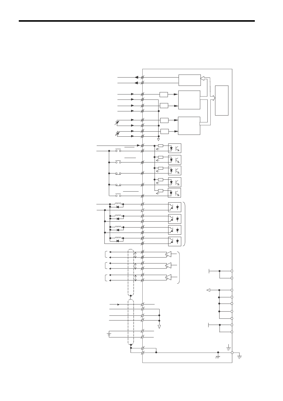
3 Wiring
3.2.3 Re-engineered SERVOPACKs for CACR-SRBY (for Absolute Encoder)
3-10
3.2.3 Re-engineered SERVOPACKs for CACR-SRBY (for Absolute Encoder)
Example: CACR-SR20BF1SFY that have replaced CACR-SR20BY1SF
P
P
P
+12 V
24 V
SERVOPACK
CACR-SR20BF1SFY
24 V
1-9
1-10
1-12
1-13
1-14
1-15
1-29
1-30
1-44
1-45
1-7
1-8
1-24
1-26
1-41
1-43
1-5
1-6
1-22
1-23
1-38
1-39
1-28
1-27
1-33
1-34
1-35
1-36
1-19
1-20
Torque monitor
F-series: 3.0 V
±10 %/100 %
Speed monitor
F-series: 2.0 V
±10 %/1000 min
-1
Speed reference input
±6 V/rated speed
Auxiliary speed reference input
±2 to ±10 V/rated speed
Reverse rotation current limit
-100 %
±10 %/+3.0 V input
Forward rotation current limit
+100 %
±10 %/-3.0 V input
1Ry
2Ry
N-LS
P-LS
9Ry
+24Vin
S-ON
P-CON
N-OT
P-OT
ALM-RST
CLT+
CLT-
TGON+
TGON-
ALM+
ALM-
S-RDY+
S-RDY-
PAO
/PAO
PBO
/PBO
PCO
/PCO
Servo ON
when 1Ry is ON
P control when 2Ry is ON
(PI control when 2Ry is OFF)
Reverse run prohibited
when N-LS is open
Forward run prohibited
when P-LS is open
Alarm reset
when 9Ry is ON
3Ry
4Ry
5Ry
6Ry
3Ry turns ON when
current limit detected
4Ry turns ON when
TG turns ON
5Ry turns OFF for a
servo alarm
6Ry turns ON when
servo ready
Phase A
Phase B
Phase C
Battery
2.8 to 4.5 V
LPF
SG
1-50
1-18
BAT
1-16
1-48
1-17
1-32
1-47
1-49
1-31
1-46
1-11
SG
-12 V
1-21
FG
5 mA
5 mA
5 mA
5 mA
5 mA
Output
Max. voltage: 30 VDC
Max. current: 30 mA
Output line driver
LS75ALS174
16-bit
D/A
LPF
16-bit
D/A
16-bit
D/A
CPU
LPF
LPF
SEN
1-4
1-2
1-3
1-1
0SEN
0V
0V
BAT0
+
1-37
CN1