2 switches to be set according to application, 3 potentiometers vr and rh – Yaskawa CACR-SRxxBF User Manual
Page 40
4.1 Setting Switches
4-3
4
4.1.1 Setting Fixed Switches (User’s Modification Prohibited)
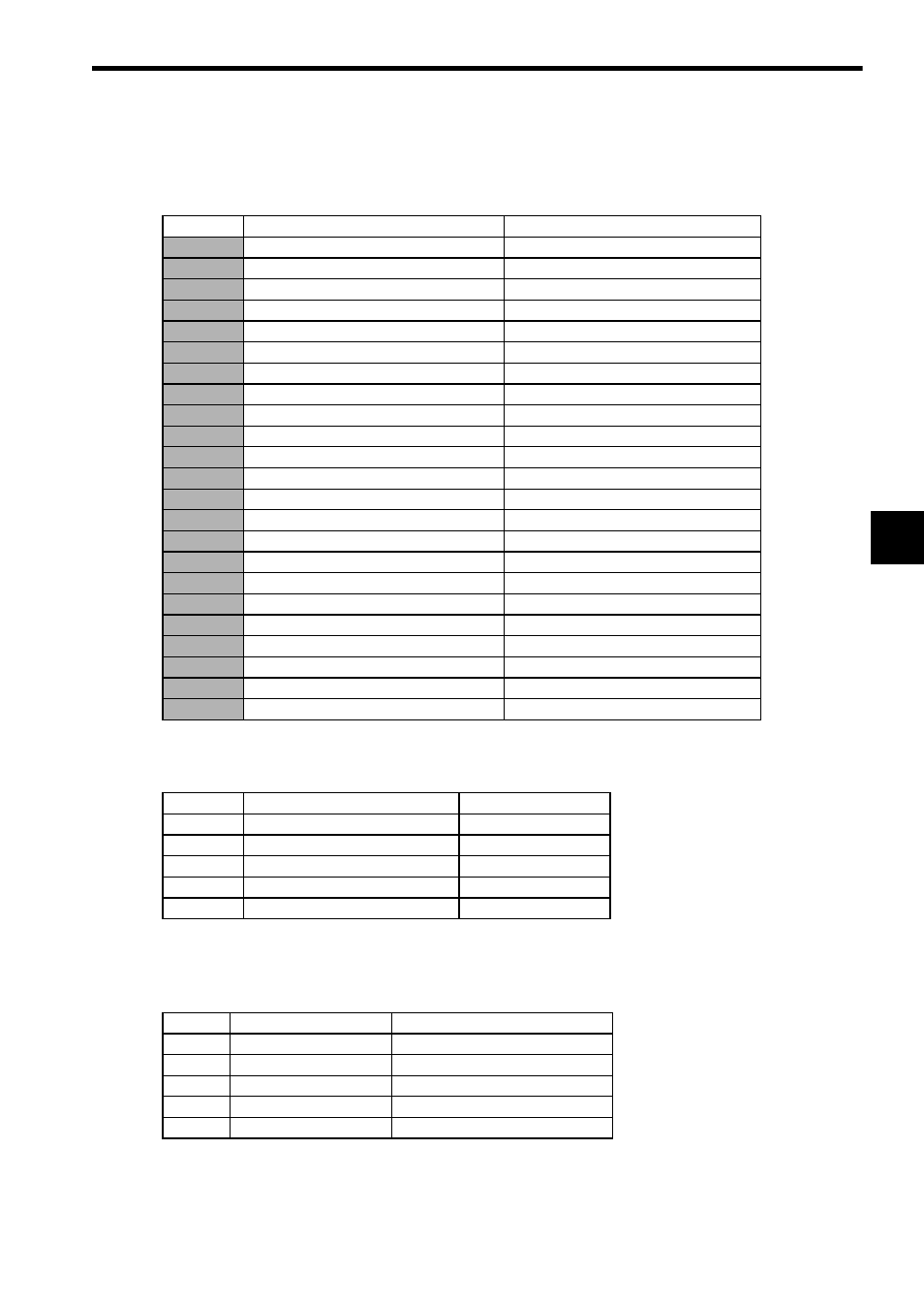
The switches listed in the table below have been set to the appropriate values before shipment.
Do not change the settings of these switches. Doing so will cause motor runaway or SERVOPACK failure.
4.1.2 Switches To Be Set According to Application
The switches listed in the table below need to be set by users according to the application.
4.1.3 Potentiometers VR and RH
Set the following potentiometers to the same scale positions as those of your conventional SERVOPACK to
obtain the same performance as before replacement.
Switch No.
Name
Remarks
CN4
Model depended function selection switch
CN5
Model depended function selection switch
CN6
Model depended function selection switch
CN7
Model depended function selection switch
CN8
Model depended function selection switch
Not mounted
CN9
Model depended function selection switch
Not mounted
CN10
Model depended function selection switch
CN11
Model depended function selection switch
CN13
Model depended function selection switch
CN14
Model depended function selection switch
CN15
Model depended function selection switch
CN16
Model depended function selection switch
CN18
Model depended function selection switch
CN20
Model depended function selection switch
CN21
Model depended function selection switch
CN22
Model depended function selection switch
CN23
Model depended function selection switch
CN24
Model depended function selection switch
CN26
Model depended function selection switch
S2
Model depended function selection switch
SL5
Speed feedback gain switching
SW3-7
Speed feedback gain switching
CN503
PC connection connector
Connector for personal computer cable
Switch No.
Name
Remarks
SL7
Torque filter switching
SW2
Frequency dividing ratio setting
SW3
Setting for CACR-SRBB/BZ
DSW1
Encoder setting
DSW5
Encoder setting
VR1
IN-B
IN-B input gain
VR6
LOOP
Speed loop gain
VR3
ZERO
Speed amplifier zero adjustment
VR4
FINE
IN-B fine adjustment
VR5
CUR
Starting current adjustment
RH2
PG5V
PG voltage adjustment