4 alarm reset button, 5 led display, 6 monitoring pins – Yaskawa CACR-SRxxBF User Manual
Page 41: 7 digital operator connector
4 Settings and Display
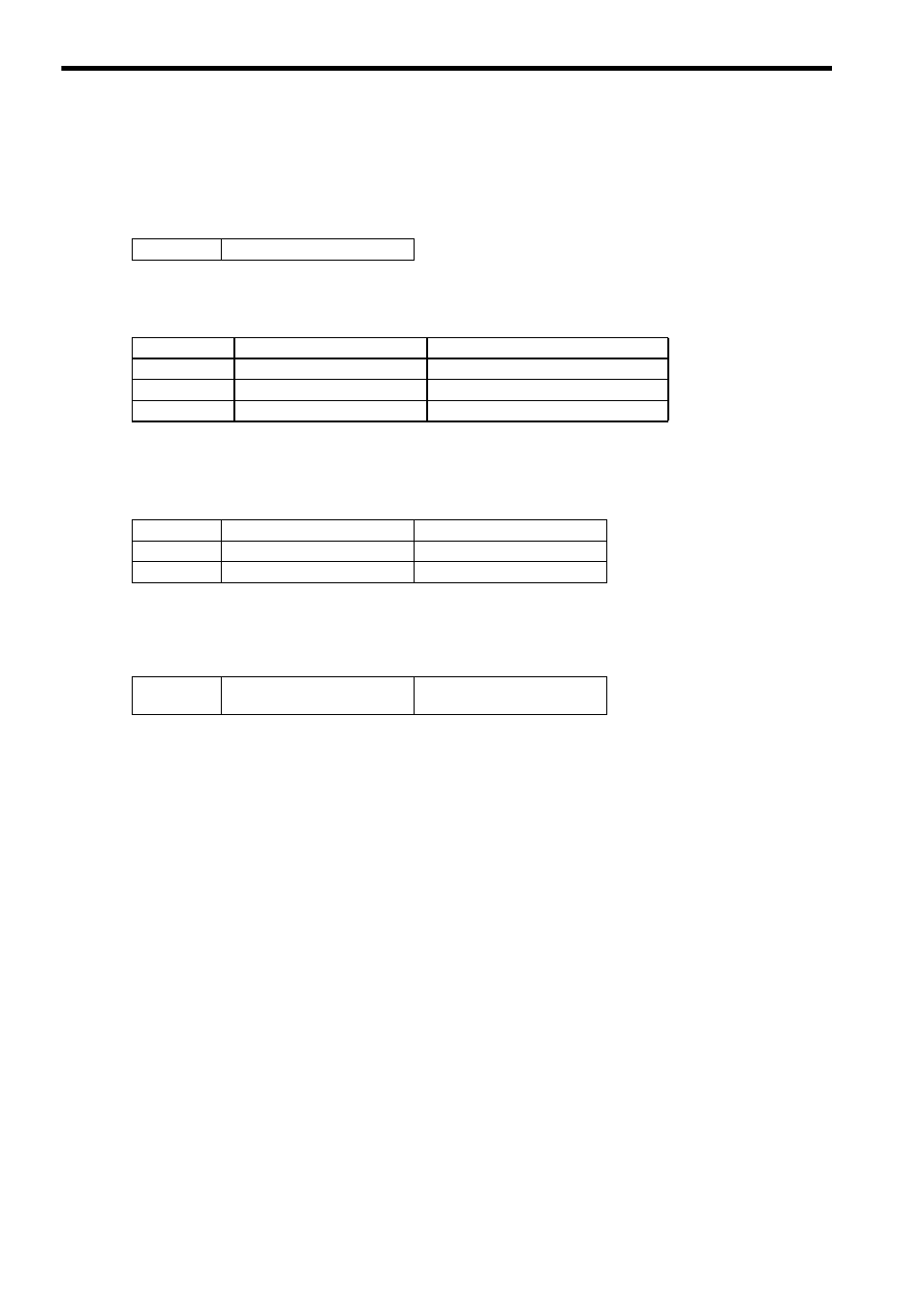
4.1.4 Alarm Reset Button
4-4
4.1.4 Alarm Reset Button
When a SERVOPACK alarm occurs, eliminate the cause and then press the RESET Button to reset the servo
alarm.
If the cause has not been eliminated, the alarm will occur again.
4.1.5 LED Display
There are four LEDs on the board as follows.
4.1.6 Monitoring Pins
The monitoring pins listed in the table below are provided for monitor signals.
The levels are the same as the conventional models.
4.1.7 Digital Operator Connector
When using the re-engineered SERVOPACK as the replacement of the conventional model CACR-SRBE or
CACR-SRBY, the connector CN3 is used to connect the digital operator JUSP-OP05A.
RESET
Alarm reset button
DS1
7-Segment LED
SERVOPACK status and alarm display
LED lamp (1)
Main circuit CHARGE LED
Main circuit with high-voltage
LED lamp (2)
Encoder conversion function
Lit in yellow during normal operation
LED lamp (3)
Encoder conversion alarm
Lit in red at alarm occurrence
TMON
For torque monitor
VTG
For speed monitor
GND
GND for monitor signal line
CN3
Connector for
Σ-III series
digital operator
Cable connector