8 p7 to p1000 terminal cross reference – Yaskawa P7 to P1000 User Manual
Page 13
8 P7 to P1000 Terminal Cross Reference
YASKAWA PL.P1000.01 P7 to P1000 - Product Transition Guide
13
8
P7 to P1000 Terminal Cross Reference
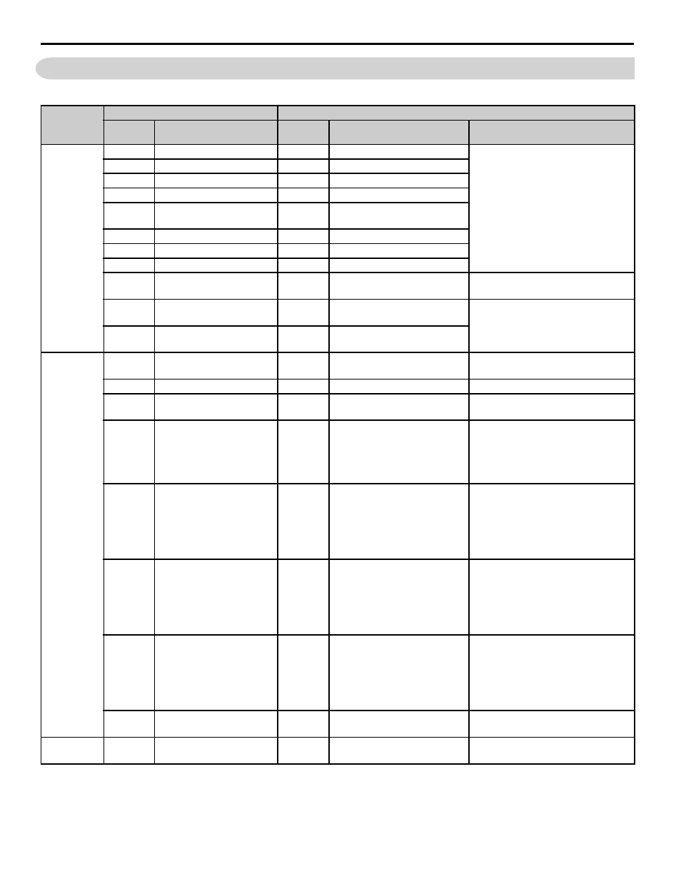
Table 7 Terminal Functions, 2-Wire Control (default)
Type
P7 Terminal
P1000 Terminal (Designations similar to P7)
P7
Terminal
Default Function
P1000
Terminal
Default Function
P1000 Description
Digital Input
Signals
S1
Forward run/stop command
S1
Forward run/stop
Multi-function inputs 1-8
Photocoupler
24 Vdc, 8 mA
Set the S3 jumper to select between
sinking, sourcing mode, and the power
supply.
S2
Reverse run/stop command
S2
Reverse run/stop
S3
External fault input
S3
External fault, N.O.
S4
Fault reset
S4
Fault reset
S5
Multi-step speed reference 1
(Master/auxiliary switch)
S5
Multi-step speed reference 1
S6
Multi-step speed reference 2
S6
Multi-step speed reference 2
S7
Jog frequency reference
S7
Jog reference
—
—
S8
External baseblock
SC
Digital input photocoupler,
(Factory connected to SP)
SC
Multi-function input common
—
SN
Digital input common
SN
Digital input power supply
0 V
24 Vdc power supply for digital inputs,
150 mA max (only when not using
digital input option DI-A3)
SP
Digital input supply +24Vdc
(Factory connected to SC)
SP
Digital input power supply
+24 Vdc
Analog Input
Signals
+V
+15 Vdc power output
+V
Power supply for analog inputs
10.5 Vdc
(max allowable current 20 mA)
-V
-15 Vdc power output
N/A
—
—
—
—
24V
+24 Vdc transducer
power supply
+24 Vdc (max. 150 mA)
—
—
RP
Multi-function pulse train input
(frequency reference)
Input frequency range: 0 to 32 kHz
Signal Duty Cycle: 30 to 70%
High level: 3.5 to 13.2 Vdc, low level:
0.0 to 0.8 Vdc
Input impedance: 3 kΩ
A1
Analog input or speed
command
A1
Multi-function analog input 1
(Frequency reference bias)
-10 to 10 Vdc, 0 to 10 Vdc
(input impedance: 20 kΩ),
4 to 20 mA, 0 to 20 mA
(input impedance: 250 Ω)
Voltage and current inputs must be
selected by Jumper S1 and H3-01.
A2
Multi-function analog input,
Add to terminal A1
A2
Multi-function analog input 2
(Frequency reference bias)
-10 to 10 Vdc, 0 to 10 Vdc
(input impedance: 20 kΩ),
4 to 20 mA, 0 to 20 mA
(input impedance: 250 Ω)
Voltage and current inputs must be
selected by Jumper S1 and H3-09.
—
—
A3
Multi-function analog input 3
(Auxiliary frequency reference)
-10 to 10 Vdc, 0 to 10 Vdc
(input impedance: 20 kΩ),
4 to 20 mA, 0 to 20 mA
(input impedance: 250 Ω)
Voltage and current inputs must be
selected by Jumper S1 and H3-05.
AC
Analog common
AC
Analog frequency reference
common
0 V
E(G)
Shield wire, optional ground
line connection point
E(G)
Ground for shielded lines and
option cards
—