Yaskawa P7 to P1000 User Manual
Page 14
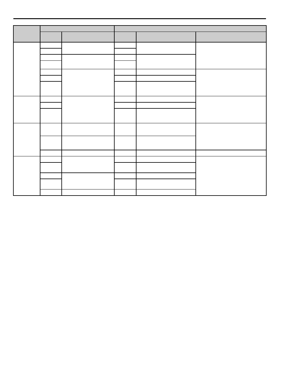
8 P7 to P1000 Terminal Cross Reference
14
YASKAWA PL.P1000.01 P7 to P1000 - Product Transition Guide
Digital
Output
Signals
M1
During run
(N.O. contact)
M1
During run
(N.O. contact)
Normally Open Multi-Function Digital
Output Contacts (Programmable):
30 Vdc (10 mA to 1 A)
250 Vac (10 mA to 1 A)
Minimum Load: 5 Vdc
M2
M2
M3
Remote/Auto Operation
(N.O. contact)
M3
Zero speed
(N.O. contact)
M4
M4
M5
Frequency agree
(N.O. contact)
MD
N.O.
Speed Agree 1 (Programmable):
30 Vdc, 10 mA to 1 A
250 Vac, 10 mA to 1 A
Minimum Load:
5 Vdc (10 mA)
N/A
ME
N.C. output
M6
MF
Output common
Fault Relay
MA
Fault output signal
(SPDT)
MA
Fault Output N.O.
Fault Output
30 Vdc (10 mA to 1 A)
250 Vac (10 mA to 1 A)
Minimum Load:
5 Vdc (10 mA)
MB
MB
N.C. output
MC
MC
Fault output common
Analog
Output
Signals
FM
Multi-function analog output
(Output frequency)
FM
Analog monitor output 1
(Output frequency)
-10 to +10 Vdc (2 mA)
0 to +10 Vdc (2 mA), or 4-20 mA
Voltage or current output must be
selected by Jumper S5 and H4-07 (FM)
or H4-08 (AM)
AM
Multi-function analog output
(Output current)
AM
Analog monitor output 2
(Output current)
AC
Analog common
AC
Monitor common
0 V
RS-485/
RS-422
R+
Modbus communication
Differential input,
PHC isolation
R+
Communications input (+)
MEMOBUS/Modbus communication:
Use an RS-485 or RS-422 cable to
connect the drive.
RS-485/RS-422 MEMOBUS/Modbus
comm. protocol: 115.2 kbps (max.)
R-
R-
Communications input (-)
S+
Modbus communication
Differential output,
PHC isolation
S+
Communications output (+)
S-
S-
Communications output (-)
IG
Signal common
IG
Shield ground
Type
P7 Terminal
P1000 Terminal (Designations similar to P7)
P7
Terminal
Default Function
P1000
Terminal
Default Function
P1000 Description