Yaskawa P7 to P1000 User Manual
Page 38
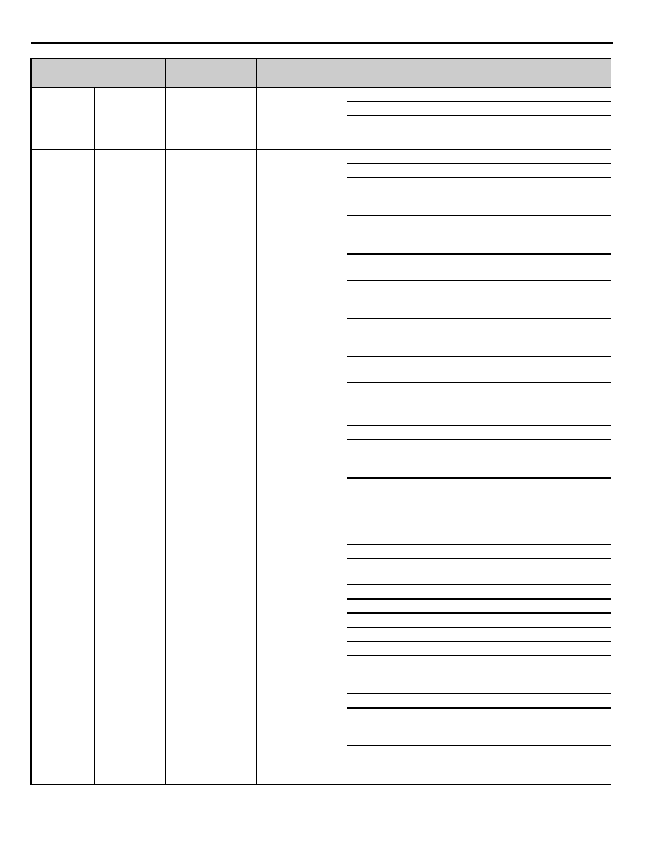
13 Appendix 2 Parameter Cross Reference
38
YASKAWA PL.P1000.01 P7 to P1000 - Product Transition Guide
Analog Input
Master
Frequency
Reference
Terminal
Selection
H3-13
0
—
—
H3-13
—
0: Main Fref TA1
—
1: Main Fref TA2
—
Multi-Function
Analog Output
Analog Output 1
Terminal FM
Monitor
Selection
H4-01
2
H4-01
102
H4-01
H4-01
—
0: Not Used
1: Frequency Ref
(100% = max. output
frequency)
101: Frequency Ref
(100% = max. output frequency)
2: Output Freq
(100% = max. output
frequency)
102: Output Freq
(100% = max. output frequency)
3: Output Current
(100% = drive rated current)
103: Output Current
(100% = drive rated current)
6: Output Voltage
(100% = 230 V or
100% = 460 V)
106: Output Voltage
(100% = 230 V or 100% = 460 V)
7: DC Bus Voltage
(100% = 400 V or
100% = 800 V)
107: DC Bus Voltage
(100% = 400 V or 100% = 800 V)
8: Output kW
(100% = drive rated power)
108: Output kW
(100% = drive rated power)
15: Term A1 Level
113: Term A1 Level
16: Term A2 Level
114: Term A2 Level
—
115: Term A3 Level
—
—
18: Mot SEC Current
(100% = Motor rated
secondary current)
601:Motor Secondary Current
20: SFS Output
(100% = max. output
frequency)
116: SFS Output
(100% = max. output frequency)
—
121: AI Output Channel 1 Level
—
122: AI Output Channel 2 Level
—
123: AI Output Channel 3 Level
—
124: Terminal RP Input
Frequency
—
408: Heatsink Temp
—
416: Motor OL1 Level
24: PI Feedback
501: PI Feedback 1
31: Not Used
31: Not Used
36: PI Input
502: PI Input
37: PI Output
(100% = max. output
frequency)
503: PI Output
(100% = max. output frequency)
38: PI Setpoint
504: PI Setpoint
51: Auto Mode Fref
(100% = max. output
frequency)
—
52: Hand Mode Fref
(100% = max. output
frequency)
—
Parameter Name
P7
P1000
Setting
Parameter
Default
Parameter
Default
P7
P1000