Yaskawa P7 to P1000 User Manual
Page 37
13 Appendix 2 Parameter Cross Reference
YASKAWA PL.P1000.01 P7 to P1000 - Product Transition Guide
37
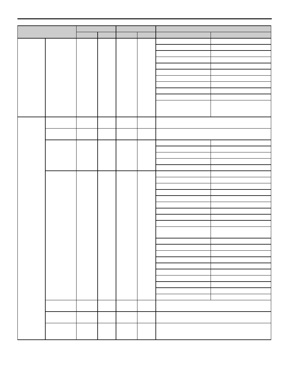
Multi-Function
Relay Output
Terminal M3-
M4 Function
Selection
H2-02
A
H2-02
1
—
4E: Braking transistor fault (rr)
—
4F: Braking resistor overheat (oH)
—
51: Sequence Timer 1
—
52: Sequence Timer 2
—
53: Sequence Timer 3
—
54: Sequence Timer 4
—
58: UL6
—
60: Fault Alarm Detection
—
71: PI2 Feedback Low
—
72: PI2 Feedback High
—
100 to 192:
Inverse Output
of 0-92
Analog Input
Terminal A1
Gain Setting
H3-02
100.0%
H3-03
100.0%
—
Terminal A1
Bias Setting
H3-03
0.0%
H3-04
0.0%
—
Terminal A2
Signal Level
Selection
H3-08
2
H3-09
2
H3-08
H3-09
0: 0 to 10 V
0: 0 to +10 V (with lower limit)
1: -10 to 10 V
1: -10 to +10 V (no lower limit)
2: 4 to 20 mA
2: 4 to 20 mA
—
3: 0 to 20 mA
Terminal A2
Function
Selection
H3-09
0
H3-10
0
H3-09
H3-10
0: Terminal A1 bias
0: Frequency bias
—
1: Frequency gain
2: Auxiliary freq ref 1
2: Auxiliary freq ref 1
—
3: Auxiliary frequency reference 2
—
4: Output voltage bias
—
5: Accel/decel time gain
—
6: DC Injection Braking current
—
7: Torque detection level
—
8: Stall Prevention level
during run
—
9: Output freq lower limit level
B: PID feedback
B: PID feedback
—
C: PID setpoint
D: Frequency Reference bias 2 D: Frequency bias 2
E: Motor temperature
E: Motor temperature PTC
—
F: Through- mode
16: PI Differential
16: Differential PID feedback
1F: Not used
1F: Through-mode
—
25: PI2 Setpoint
—
26: PI2 Feedback
Terminal A2
Gain Setting
H3-10
100.0%
H3-11
100.0%
—
Terminal A2
Bias Setting
H3-11
0.0%
H3-12
0.0%
—
Analog Input
Filter Time
Constant
H3-12
0.03 s
H3-13
0.03 s
—
Parameter Name
P7
P1000
Setting
Parameter
Default
Parameter
Default
P7
P1000