Yaskawa VS mini J7 Series User Manual
Page 90
90
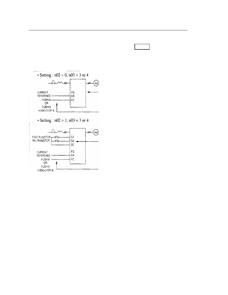
Current reference selection
After changing DIP switch (SW8) to the “I” side, PRESS
on the digital
operator, then set the following parameters.
4-20mA…n03 = 3
0-20mA…n03 = 4
Frequency reference gain (n41)/bias (n42) can be set even when current reference input
is selected. For details, refer to “Adjusting speed setting signal” on page 69.
PRGM
Press the digital operator keys to run or stop
the inverter. Switch run and stop direction by
setting F/R LED.
Set frequency by the analog current signal
[0-100% (max frequency)/4-20mA or 0-
20mA] connected to the control circuit
terminal.
Set run/stop and FWD/REV run with
switching device connected to the control
circuit terminal.
Multi-function input terminal S2 is set to
Reverse run/stop (n36 = 2).
Set frequency by the analog current signal
[0-100% (max. frequency)/4-20mA or 0-
20mA] connected to the control circuit
terminal.