Amprobe AMB-110 Insulation-Resistance-Tester User Manual
Page 18
13
where:
Ut ........... Test voltage
IL ............ Leakage current (resulted by surface dirt and moisture)
IM ........... Material current (resulted by material conditions)
IA............ A-meter current
• Result without using GUARD terminal: RINS = Ut / IA = Ut / (IM + IL) …incorrect result.
• Result using GUARD terminal: RINS = Ut / IA = Ut / IM ……correct result.
• It is recommended to use the GUARD connection when high insulation resistance (>10G )
are measured.
Note:
• The guard terminal is protected by an internal impedance (400 K).
• The instrument has two guard terminals to allow easy connection of shielded measuring
leads.
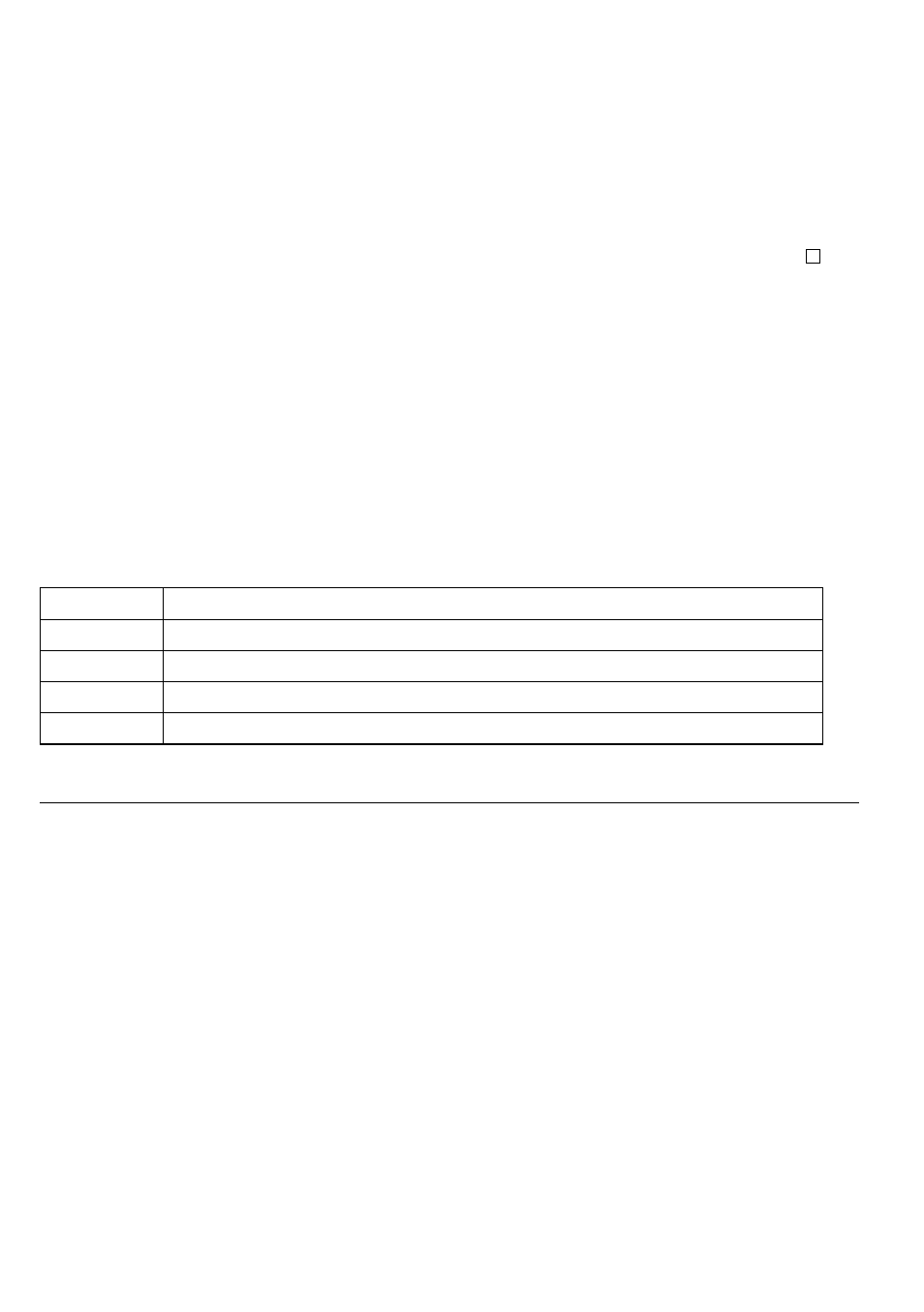
Filter options
Filters are built in to reduce the influence of noise on measurement results. This option enables
more stable results especially when dealing with high Insulation Resistances (Insulation Resistance,
Diagnostic Test, Step Voltage). In these functions, the status of the filter option is shown in the
top right corner of the LCD screen. The Table 2. below contains a definition of the individual filter
options:
Filter option
Meaning
Fil0
Low pass filter with cut off frequency of 0.5 Hz in signal line.
Fil1
Additional low pass filter with cut off frequency of 0.05 Hz in the signal line.
Fil2
Fil1 with increased integrating time (4 s).
Fil3
Fil2 with additional cyclic averaging of 5 results.
Table 2. Filter options
THE PURPOSE OF FILTERING
In simple terms the filters smooth the measured currents by means of averaging and bandwidth
reduction. There are various sources of disturbance:
• AC currents at the mains frequency and its harmonics, switching transients etc, cause
the results to become unstable. These currents are mostly cross talk through insulation
capacitances close to live systems,
• Other currents induced or coupled in the electromagnetic environment of the insulation
under test.
• Ripple current from internal high voltage regulator,
• Charging effects of high capacitive loads and / or long cables.
Voltage changes are relatively narrow on high resistance insulation, so the most important point is
to filter the measured current.
Note
Any of the selected filter options increases the settling time with Fil1 to 60 s, Fil2 to 70 s, and
Fil3 to 120 s.
• It is necessary to pay close attention to the selection of time intervals when using the filters.
• The recommended minimum measuring times when using filters are the settling times of the
selected filter option.