Amprobe AMB-110 Insulation-Resistance-Tester User Manual
Page 26
21
Displayed symbols:
DIAGNOSTIC TEST
Name of selected function
Fil0 (Fil1, Fil2, Fil3)
Filter type enabled, see the section of Configuration
5000V
Set test voltage – step 25 V
U=5295
Actual test voltage – measured value
I=55.6nA
Actual test current – measured value
10.5Ge
Insulation Resistance – result
C=2.1nf
Capacitance of measured object
Tr:00min 15s
Set timer value
Bar
Analogue representation of Riso result
R15sec=10.6Ge
Resistance value measured after set time 1
R01min=10.5Ge
Resistance value measured after set time 2
R10min=10.5Ge
Resistance value measured after set time 3
DAR=1.67
DAR as ratio of R1min / R15s
PI=1.21
PI as ratio of R03/R02
DD=__
DD result
Note
• A high-voltage warning symbol appears on the display during the measurement to warn the
operator of a potentially dangerous test voltage.
• The value of the capacitance is measured during the final discharge of the test object.
• If enabled, the instrument measures Dielectric Discharge (DD) when the capacitance is in the
range of 5 nF to 50 F.
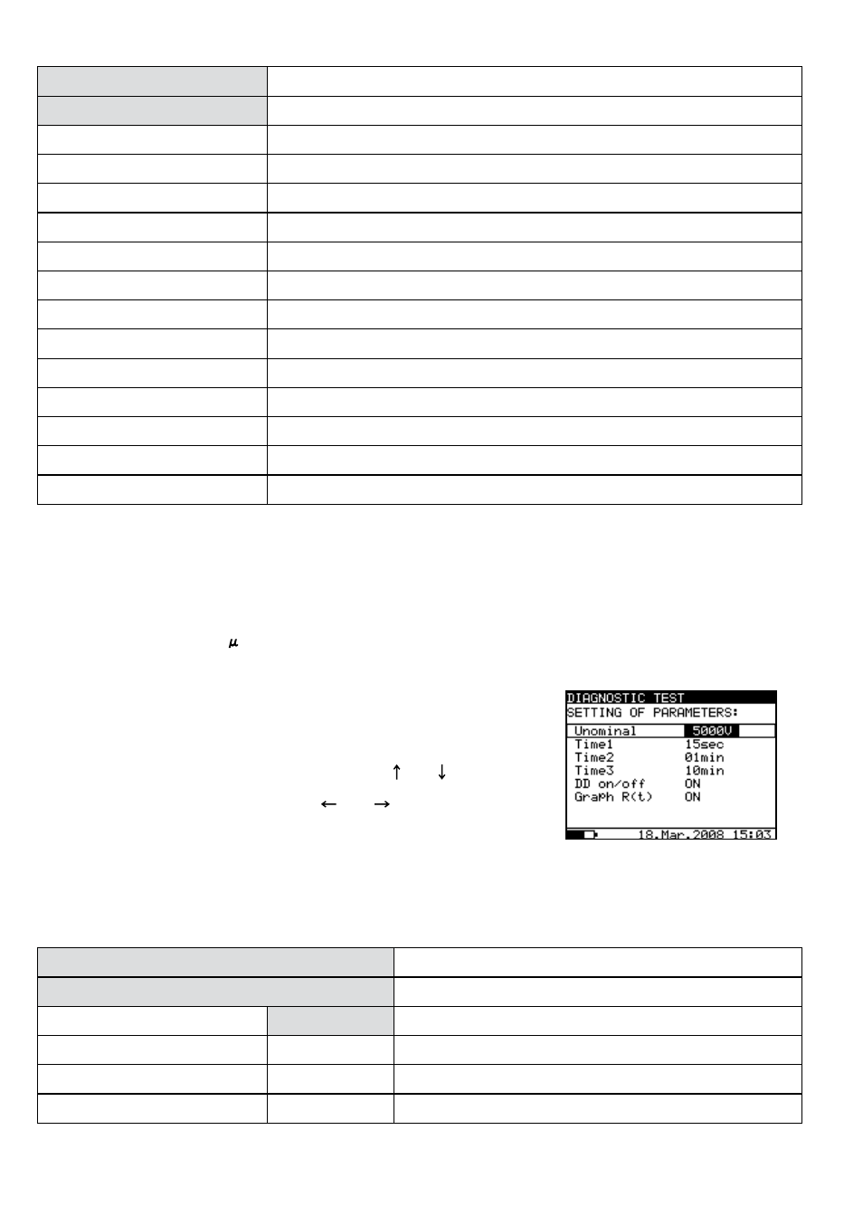
Setting up the parameters of the Diagnostic Test:
• Press the SELECT key, (the Set-up menu appears on display,
see the Fig. 16).
• Select the parameter) to be set using the and keys;
• Adjust the parameter using the and keys.
• Complete the set-up adjustments by pressing either the
ESC key or START key (to run the measurement directly).
The settings displayed last are stored.
Displayed symbols:
DIAGNOSTIC TEST
Name of selected function
SETTING PARAMETERS:
Unominal
5000 V
Set test voltage – step 25 V
Time1
01min
Time node to take R1min result
Time2
02min
Time node to take R1min result and calculate DAR
Time3
03min
Time node to take R3min result and calculate PI
Fig. 16 Set-up menu in
Diagnostic Test