Amprobe AMB-110 Insulation-Resistance-Tester User Manual
Page 17
12
Withstanding voltage test
Some standards allow the use of a DC voltage as an alternative to AC withstanding voltage
testing. For this purpose the test voltage has to be present across the insulation under test for a
specific time. The insulation material only passes if there is no breakdown or flash over. Standards
recommend that the test starts with a low voltage and reaches the final test voltage with a slope
that keeps the charging current
under the limit of the current threshold. The test duration normally takes 1 min.
Withstanding voltage test or dielectric test is usually applied for:
• Type (acceptance) tests when a new product is being prepared for manufacture,
• Routine (production) tests for the verification of safety on each product,
• Maintenance and after service tests for any equipment where the insulation system can be
exposed to degradation.
Some examples for DC withstanding test voltage values:
Standard (only sample values)
Voltage
EN/IEC 61010-1 CAT II 300 V basic insulation
1970 V
EN/IEC 61010-1 CAT II 300 V double insulation
3150 V
IEC 60439-1 (clearance between live parts…), withstanding impulse voltage 4 kV, 500 m
4700 V
IEC 60598-1
2120 V
Humidity and insulation resistance measurements
When testing outside the reference ambient conditions, the quality of the insulation resistance
measurements can be affected by humidity. Humidity adds leakage paths onto the surface of the
complete measuring system, (i.e. the insulator under test, the test leads, the measuring instrument
etc). The influence of humidity reduces accuracy especially when testing very high resistances. The
worst conditions arise in environments containing high condensation, which can also reduce safety.
In the case of high humidity, it is recommended to ventilate the test areas before and during the
measurements. In the case of condensed humidity the measuring system must dry and it can take
several hours or even few days to recover.
Guard terminal
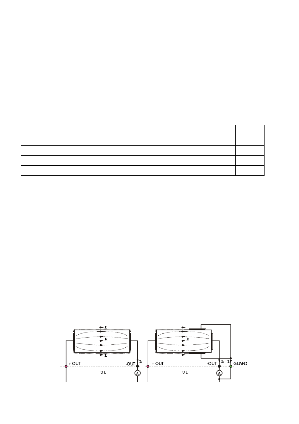
The purpose of the GUARD terminal is to lead away potential leakage currents (e.g. surface
currents), which are not a result of the measured insulation material itself but are a result of
the surface contamination and moisture. This current interferes with the measurement i.e.
the Insulation Resistance result is influenced by this current. The GUARD terminal is internally
connected to the same potential as the negative test terminal (black one). The GUARDs test clip
should be connected to the test object so as to collect most of the unwanted leakage current, see
the figure Fig. 7 below.
Fig. 7 Connection of GUARD terminal to measured object