Avago Technologies LSI53C825AE User Manual
Page 233
DC Characteristics
6-5
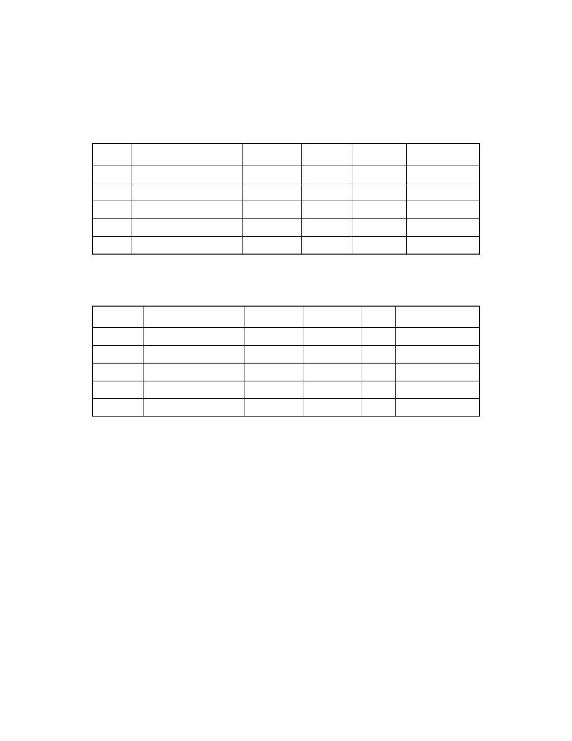
Table 6.10
Bidirectional Signals
1
—AD[31:0], C_BE[3:0], FRAME/, IRDY/, TRDY/,
DEVSEL/, STOP/, PERR/, PAR/
Symbol
Parameter
Min
Max
Unit
Test Conditions
V
IH
Input high voltage
2.0
V
DD
+0.5
V
–
V
IL
Input low voltage
V
SS
−
0.5
0.8
V
–
v
OH
Output high voltage
2.4
V
DD
V
16 mA
v
OL
Output low voltage
V
SS
0.4
V
16 mA
I
OZ
3-state leakage
−
10
10
µ
A
–
1. All the signals in this table have 25
µ
A pull-ups that are enabled when TESTIN is low.
Table 6.11
Bidirectional Signals
1
—GPIO0_FETCH/, GPIO1_MASTER/, GPIO2_MAS2/,
GPIO3, GPIO4
Symbol
Parameter
Min
Max
Unit
Test Conditions
V
IH
Input high voltage
2.0
V
DD
+0.5
V
–
V
IL
Input low voltage
V
SS
−
0.5
0.8
V
–
V
OH
Output high voltage
2.4
V
DD
V
−
16 mA
V
OL
Output low voltage
V
SS
0.4
V
16 mA
I
OZ
3-state leakage
−
10
10
µ
A
–
1. All the signals in this table have 100
µ
A pull-ups that are enabled when TESTIN is low.