Table 3.1 – Avago Technologies LSI53C825AE User Manual
Page 74
3-4
Signal Descriptions
There are four signal type definitions:
I
Input, a standard input-only signal.
O
Output, a standard output driver (typically a Totem Pole Output).
T/S
3-state, a bidirectional, 3-state input/output signal.
S/T/S
Sustained 3-state, an active LOW 3-state signal owned and driven by
one and only one agent at a time.
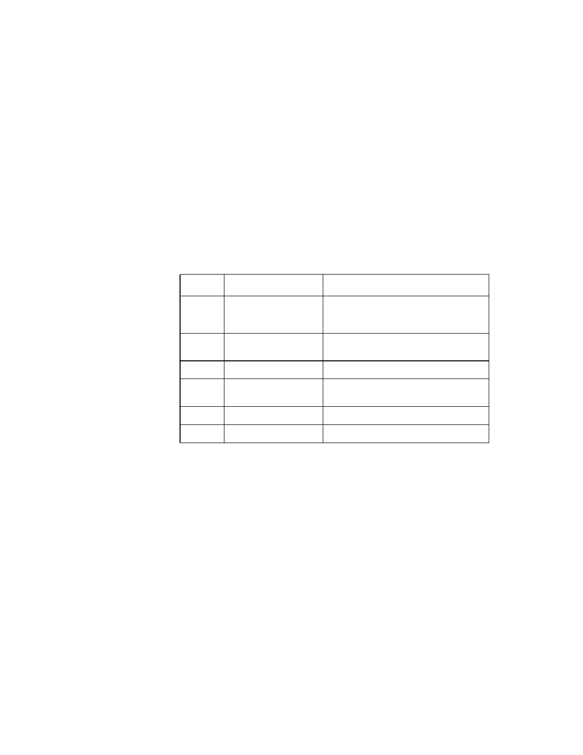
Table 3.1
LSI53C825A, LSI53C825AJ, LSI53C825AE, and
LSI53C825AJE Power and Ground Pins
Symbol
Pin No.
Description
V
SS
4, 10, 14, 18, 23, 27,
31, 37, 42, 48, 69, 79,
123, 133, 152, 158
Ground to the PCI I/O pins
V
DD
8, 33, 45,
63, 74, 84,
118, 128, 138
, 155
Power supplies to the Standard I/O pins
V
DD-I
1
1. These pins can accept a VDD source of 3.3 or 5 Volts. All other VDD pins
must be supplied 5 Volts.
8, 21, 33, 45, 155
V
DD
pad for PCI I/O pins
V
SS
-S
88, 93, 99, 104, 109,
114
Ground to the SCSI bus I/O pins
V
SS
-C
55, 146
Ground to the internal logic core
V
DD
-C
51, 149
Power supplies to the internal logic core