Chapter 2. hardware installation, 1 hardware description, 1 the top / bottom panel – PLANET WNAP-6308 User Manual
Page 19: Chapter 2, Hardware installation, Hardware description, Top/bottom panel, Igure, Ppearance, Op / b
User Manual of WNAP-6308
-9-
Chapter 2. Hardware Installation
Please follow the instructions below to connect the WNAP-6308 to the existing network devices and your
computers.
2.1 Hardware Description
Dimensions: 45 x 169 mm (Φ x H)
Figure 2-1 Appearance
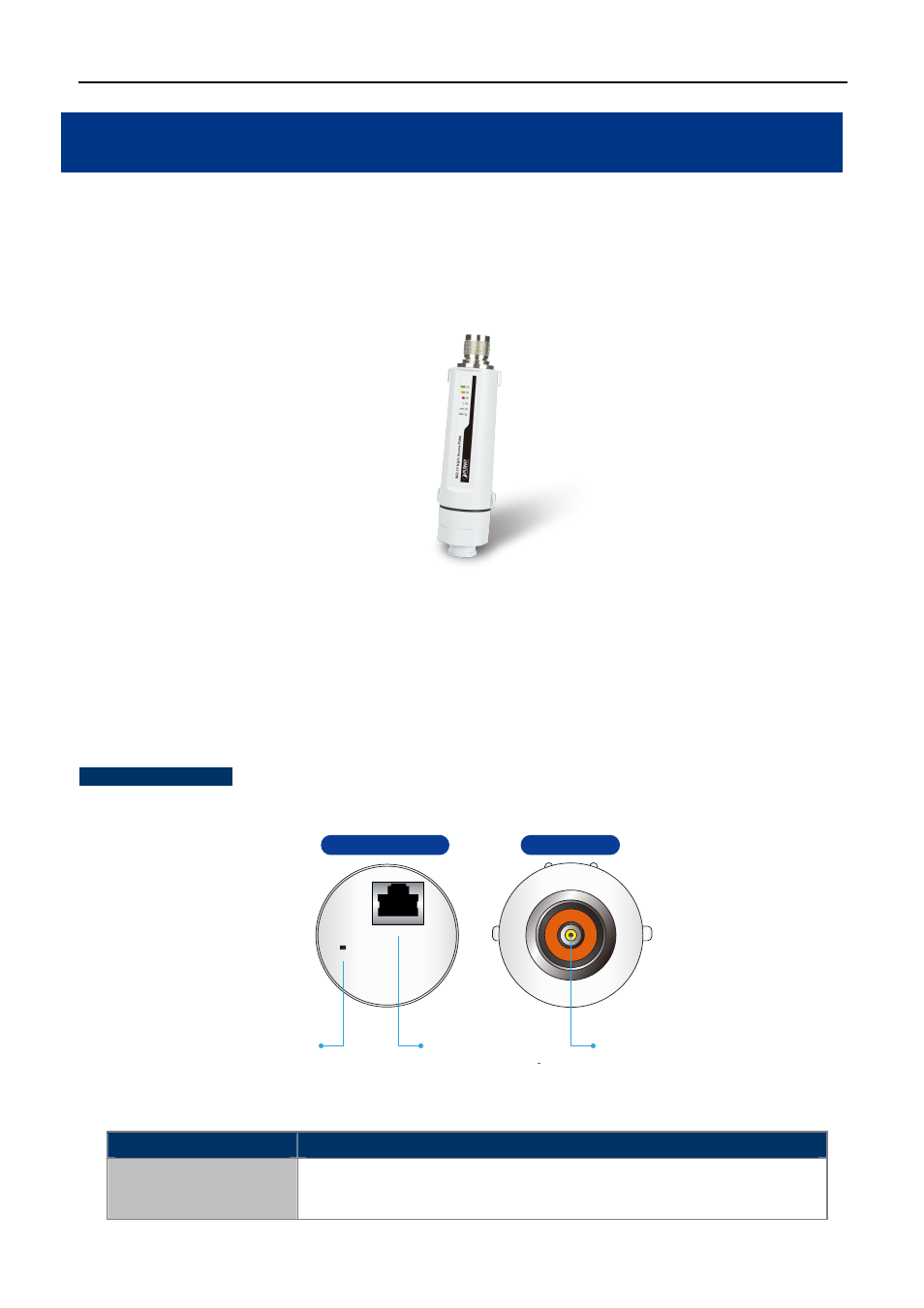
2.1.1 The Top / Bottom Panel
The top and the bottom panels provide the physical connectors connected to the antenna, power injector
and any other network device.
Figure 2-2
shows the top and the bottom panels of the WNAP-6308.
Top & Bottom
Panel
Figure 2-2 Top / Bottom Panel
Object
Description
PoE (LAN Port)
10/100Mbps RJ-45 port , Auto MDI/ MDI-X & Passive PoE supported.
(Pin 4,5 VDC+; Pin 7,8 VDC-)
N-Type (Male)
Antenna Connector
LAN(Passive PoE)
Pin4,5(+);Pin7,8(-)
Reset Button
PoE
Reset
Top View
Bottom View