ProSoft Technology MVI69-103M User Manual
Page 75
Reference MVI69-103M
♦ CompactLogix or MicroLogix Platform
IEC 60870-5-103 Master Communication Module
ProSoft Technology, Inc.
Page 75 of 131
November 3, 2008
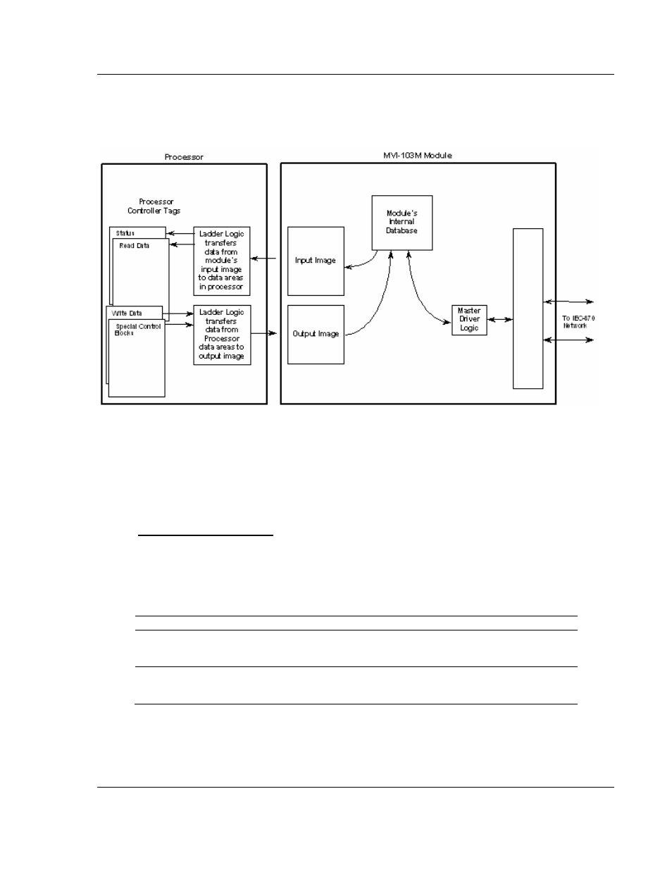
The following illustration shows the data transfer method used to move data
between the CompactLogix or MicroLogix processor, the MVI69-103M module,
and the serial network.
All data transferred between the module and the processor over the backplane is
through the input and output images. Ladder logic must be written in the
CompactLogix or MicroLogix processor to interface the input and output image
data defined in the controller tags. The user is responsible for handling and
interpreting all data received on the application ports and transferred to the input
image.
Data Types and Mapping
When interfacing data in the processor to that of the IEC 60870-5-103 protocol, it
is important that the user understand the mapping of the data types to their
corresponding representation in the modules database. The following table lists
the data types supported by the module and their associated storage
representation:
Type ID
Description
Data Representation
1
Time-tagged messages with each data
point represented by two bits.
Dual-bit status (7.2.6.5 with 00b (0 decimal) =
not used, 01b (1 decimal) = Off, 10b (2
decimal) = On and 11b (3 decimal) = not used
2
Time-tagged messages with relative
time with each point represented by
two bits.
Dual-bit status (7.2.6.5 with 00b (0 decimal) =
not used, 01b (1 decimal) = Off, 10b (2
decimal) = On and 11b (3 decimal) = not used