ProSoft Technology MVI56-DFCM User Manual
Page 83
MVI56-DFCM ♦ ControlLogix Platform
Reference
DF1 Half/Full Duplex Master/Slave Serial Communication Module
User Manual
ProSoft Technology, Inc.
Page 83 of 106
September 24, 2014
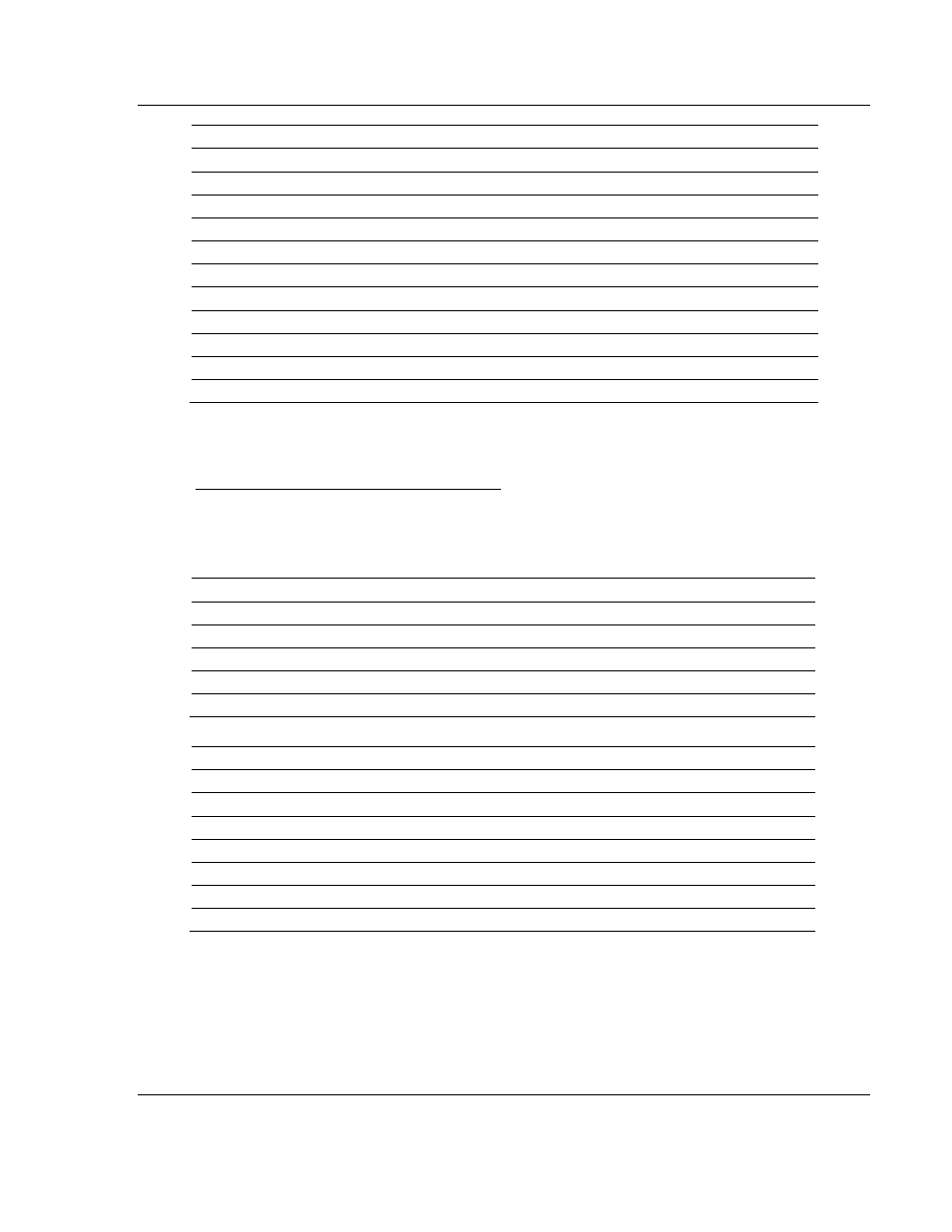
Offset
Description
Length
134 to 145
Command Definition
12
146 to 157
Command Definition
12
158 to 169
Command Definition
12
170 to 181
Command Definition
12
182 to 193
Command Definition
12
194 to 205
Command Definition
12
206 to 217
Command Definition
12
218 to 229
Command Definition
12
230 to 241
Command Definition
12
242 to 248
Spare
7
249
-6000 to -6004 and -6100 to -6104
1
Each of these blocks must be handled by the ladder logic for proper module
operation.
Module Configuration Data Block (9000)
This block sends general configuration information from the processor to the
module. The data is transferred in a block with an identification code of 9000.
Module Configuration (Write Block)
Offset
Description
Length
0
Configuration Block ID number (value 9000)
1
1 to 6
Backplane Set Up
6
7 to 32
Port 1 Configuration
26
33 to 58
Port 2 Configuration
26
59 to 247
Spare
189
The read block used to request the configuration has the following structure:
Offset
Description
Length
0
Reserved
1
1
Configuration Block ID number (value 9000)
1
2
Module Configuration Errors
1
3
Port 1 Configuration Errors
1
4
Port 2 Configuration Errors
1
5 to 248
Spare
244
249
-2 or -3
1
If there are any errors in the configuration, the bit associated with the error will be
set in one of the three configuration error words. The error must be corrected
before the module starts operating.